The double sided tape used around the perimeter will keep a constant tension for the long haul?
I can see it used on sides as very little tension is needed because of the curve.
Will you be gluing the final stator top and bottom sections to keep it from moving over time?
Regards
David
That's how they are from the factory, just DS tape all around. Actually the sides would take more stress than the ends. Once they are taken apart, the front stator has less curvature than the rear one
Last edited:
Thanx for the info as I have SL3,s that for now don't need any help yet
I am in the process of rebuilding a second pair of Quad 57 that need a quite different and more difficult tension arangement and thought the ML,s were similiar
Good to know and appreciate your posts and efforts
Regards
David
I am in the process of rebuilding a second pair of Quad 57 that need a quite different and more difficult tension arangement and thought the ML,s were similiar
Good to know and appreciate your posts and efforts
Regards
David
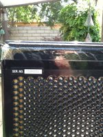
Yes, double sided tape all around, but there was additional tape on top bottom too to hold the vertical tension...see pic
Yes, that cello tape holds the Mylar to the rear stator. I'm guessing they did that because of the longitudinal tension of the Mylar. I did the same, in fact I did it all around just as an added precaution
You may not have enough bias voltage, but if it sounded good before, no reason to think something is now wrong with the interface.
I would check for leaks off the mylar. Do you know the Neon lamp bias charge circuit they have on Quads? I will post the schematic. It about $15 of parts from Rat Shack. It blinks when bias charge is on. If blinks quickly, or stays on, you have a bias leak from mylar to stator(s).
Look along the edges of the stators....look for chips exposing the bare metal underneath the enamel. Cover with black nail polish - couple coats. If you leak enough voltage off the mylar, you will get poor spl and never sound right.
Ok, thanks. There weren't any chips in the black coating at all, I did a very thorough inspection and it's coated 100%. What else will cause leaks off the mylar? The Licron seemed to have a nice even coat. I wonder if they aren't producing the voltage they should? What goes wrong in the voltage ladder, can the diodes go bad?
Last edited:
Hi,
how do You apply the bias voltage? Metal charge ring or simply open wire end after ML style? Make sure that there is really a connection between Licron and wire. Btw. Most self adhesive copper foils use non-conductive glue, and I wouldn´t bet on the functioning and longterm stability of those with conductive glue layer.
Test the functioning with open panel, i.e. just the stator the diaphragm is mounted to against the diaphragm. Applying the bias and the membrane will be deflected towards the stator, eventually sticking to it.
jauu
Calvin
Hi,
how do You apply the bias voltage? Metal charge ring or simply open wire end after ML style? Make sure that there is really a connection between Licron and wire. Btw. Most self adhesive copper foils use non-conductive glue, and I wouldn´t bet on the functioning and longterm stability of those with conductive glue layer.
Test the functioning with open panel, i.e. just the stator the diaphragm is mounted to against the diaphragm. Applying the bias and the membrane will be deflected towards the stator, eventually sticking to it.
jauu
Calvin
I installed a copper wire charge ring all around the perimeter, it charges almost instantly so I don't think contact with the membrane is an issue
Well, I got them all put back together, and while they work ok, they sound rather dull, nowhere near the detail of the Monoliths I also own. Does anything go bad in the power supply that would affect this?
By dull do you mean the top end sounds rolled off?
If so, any chance you installed thicker mylar than what was originally used?
The thicker(ie heavier) the mylar the sooner the -6db/oct HF roll off starts.
Here is link to measurements of HF roll off for 3.8µm, 6.0µm, and 12.0µm diaphragms:
http://www.diyaudio.com/forums/plan...tatic-speakers-microphones-5.html#post3427260
I beleive the original Mylar thickness was 6 microns, so cannot be thicker Mylar.
Are the stators clamped tight?
Exactly what I used and they are tight all around
DS Tape Sticking
Re: long term "sticktion" of DS tape, pay close attention to Jazzman's diagram showing how the DS tape extends beyond the edges of the stators and is wrapped over the edges and taped down with polyester tape. I didn't notice Charlie changed his original procedure until recently and consequently I am working on my fourth rebuild now (the other three failed due to tape not adhering to the stators.) The DS tape will not hold the Mylar tension unless it is wrapped over the edges. I also have noticed the tape stuck much better to stators coated with Rustoleum gloss black as a final coat, rather than gloss clear coat that I currently use. After the panels are completed,I will clamp them to new maple frames I have built. This should help to insure the ESL panels don't pull apart. HTH.
Re: long term "sticktion" of DS tape, pay close attention to Jazzman's diagram showing how the DS tape extends beyond the edges of the stators and is wrapped over the edges and taped down with polyester tape. I didn't notice Charlie changed his original procedure until recently and consequently I am working on my fourth rebuild now (the other three failed due to tape not adhering to the stators.) The DS tape will not hold the Mylar tension unless it is wrapped over the edges. I also have noticed the tape stuck much better to stators coated with Rustoleum gloss black as a final coat, rather than gloss clear coat that I currently use. After the panels are completed,I will clamp them to new maple frames I have built. This should help to insure the ESL panels don't pull apart. HTH.
Re: long term "sticktion" of DS tape, pay close attention to Jazzman's diagram showing how the DS tape extends beyond the edges of the stators and is wrapped over the edges and taped down with polyester tape. I didn't notice Charlie changed his original procedure until recently and consequently I am working on my fourth rebuild now (the other three failed due to tape not adhering to the stators.) The DS tape will not hold the Mylar tension unless it is wrapped over the edges. I also have noticed the tape stuck much better to stators coated with Rustoleum gloss black as a final coat, rather than gloss clear coat that I currently use. After the panels are completed,I will clamp them to new maple frames I have built. This should help to insure the ESL panels don't pull apart. HTH.
I should add and clarify:
My second generation panels, which I am still using, still has the foam tape merely overhanging the stator edges by 1/16", followed by over-wrapping the edges with 2-mil polyester packing tape. This arrangement is still holding tension on the diaphragms 5 years later so it does work-- but it might not have worked if the foam tape were not fresh (good tack) when applied, and/or if the diaphragm coating were not solvent cleaned to promote adhesion to the tape. Some paints have more surface energy than others, which helps adhesion.
I decided to recommend using wider foam tape and wrapping it over the stator edges for two reasons. First, it should hold diaphragm tension even if the foam tape doesn't stick all that well to the stator.
Secondly, a conversation I had with our friend Steve (a.k.a. Bolserst) lead me to believe that the high dielectric-strength polyester tape may actually reflect and focus the corona back onto the stator edge (and possibly breaking down the stator coating). It follows then, that by first wrapping the stator edges with the lower-dielectric foam tape, followed by polyester tape over the top, the corona would not be as intensely reflected back onto the stator edges... yet the corona is still confined enough to prevent arcing to the opposing stator.
I actually have not built a panel with the wider foam tape wrapped over the stator edges as shown in my updated sketch, but if I ever have to redo my panels, this is how I will do it. I might even use 1.5" wide tape and wrap a full .75" over the stator edge. And it may be easier to get the foam tape to stick to the outside of the stator if it were wrapped over the edges before tensioning and bonding to the diaphragm (the excess diaphragm would then be wrapped over the stator edges after tensioning). In any case, I'm now convinced it's better to wrap the foam tape over the stator edges.
Last edited:
- Status
- This old topic is closed. If you want to reopen this topic, contact a moderator using the "Report Post" button.
- Home
- Loudspeakers
- Planars & Exotics
- Martin Logan CLS membrane re-do