Hi,
. The only thing I'm still missing ...... and that's the point You Gerald my friend, come into play, are transparent toroids
jauu
Calvin
One can use mirrors to hide non-transparent things like David Copperfield does.
I would not use laser on acrylic: it creates extreme stress at the edges and one have to anneal the whole thing and still you'll get the whole bunch of whisker kinda cracks. Proper router bit would yield any kind of edge you like.
I have used laser cut acrylic for all of the ribs, spacers and other structural members for my ESL, without any sign of any problems - so far at least.
Hi,
nice Idea Alex, as always from You. ;-)
The idea only suffers from that I haven´t got the smart looks and mysterious aura of Mr. Copperfield, nor can I afford those beautiful assistances holding the mirrors.
The mirrors would rather crack in my faces presence. For me the speaker needs to do all of the trick alone *lol*
jauu
Calvin
It's from my own sad experience,I have used laser cut acrylic for all of the ribs, spacers and other structural members for my ESL, without any sign of any problems - so far at least.
if you do not believe:
Having problem gluing laser-cut acrylic parts
or that
Problems Gluing Laser Cut Acrylic
Also it's fair to say that three main kinds of polymethylmethacrylate exist: emulsion solution and bulk(cast). They differ in the aspect in question.
It's from my own sad experience,
if you do not believe:
Having problem gluing laser-cut acrylic parts
or that
Problems Gluing Laser Cut Acrylic
Also it's fair to say that three main kinds of polymethylmethacrylate exist: emulsion solution and bulk(cast). They differ in the aspect in question.
In a previous prototype of a curved esl I used curved plexiglas spacers. I did not observe any problems upon solvent welding. However, the plexiglas did receive a high temperature treatment after the laser cutting which lowers internal tensions so that might explain something.
Alexberg
Thanks very much for the links - most informative.
As I say, its not been my experience so far. The particular acrylic I used is sold under the brand name shinkolite, or something like that. It has tighter tolerances on the thickness of the material than the normal acrylic sheet. It is possible that it has also been annealed during manufacture to reduce intrernal stresses (does anyone know?). I also used a very low viscosity methacrylate glue to attach the acrylic to the PCBs - not much else worked. I may have fortunate in my choice of glue too.
I have had the experiences you describe with polycarbonate - machined edges on polycarbonate tear like tissue paper. If you try washing machined polycarbonate parts in an utrasonic bath they shatter into dozens of small bits - quite stunning actually.
I have had the experiences you describe with polycarbonate - machined edges on polycarbonate tear like tissue paper. If you try washing machined polycarbonate parts in an utrasonic bath they shatter into dozens of small bits - quite stunning actually.
Interesting...now where can I get my hands on an ultrasonic bath.

I had switched from acrylic to Lexan(polycarbonate) because it handled cutting and drilling without chipping or cracking much better than acrylic.
Interesting...now where can I get my hands on an ultrasonic bath.
I had switched from acrylic to Lexan(polycarbonate) because it handled cutting and drilling without chipping or cracking much better than acrylic.
Yeah I have too had serious problems with acrylic. It was almost unusable.
Some materials I have tried:
1) Polystyrene plexiglass.much better than acrylic, still develops cracks over time and pressure.
2) Axrylic plexiglass. Too brittle IMO.
3) Rigid PVC sheets. Good material and resists cracking, however high epsilon(~4)
4) Low density PVC. Much lower epsilon and resists cracking. Not as strong and may have worse tolerances
What purpose does it serve? Cavitation can destroy almost any material. http://www.absotecthailand.com/Cavitation.pdfIf you try washing machined polycarbonate parts in an utrasonic bath they shatter into dozens of small bits - quite stunning actually.
I would talk to billboard or light signs companies: they do know what and how to cut glue and fix various plastic parts acrylic included.
Golfnut (and others),
I hope this isn't too off topic. I'm interested in implementing a similar approach in a sectioned planar magnetic driver, rather than an ESL. I'm sure there's no acoustic reason it shouldn't work similarly. Any suggestions on the best circuit topology? I'm envisioning vertical parallel aluminum conductors immersed in a magnetic field. With the foil I have on hand it's convenient to have individual conductors with resistances on the order of 1 or 2 ohms. I can run multiple physically parallel, but electrically in series, conductors in each magnet gap to increase the resistance if necessary.
Few
Hi Few
I’m sorry I don’t know enough about ribbon-type transducers to be able to give you hard advice on other types of segmented planar radiators, but I can perhaps point to a few things that you need to think about. Perhaps there are some books or DIYers about that will answer some of these questions
The ESL strip radiator is essentially a constant pressure source (because the diaphragm mass is so small), whereas the traditional electromagnetic speaker is a constant volume-velocity source because it’s behaviour is dominated by the cone mass. It may be that the ribbon is sufficiently light it too can be treated as a pressure source.
A line-source, like the single strip ESL, has an awkward sqrt(f) response characteristic, which is corrected by the RC transmission line structure of the segmented ESL. If the same awkward frequency dependence applies to the segmented planar electromagnetic radiator, then it may be that there is a similar RL transmission line structure that will equalise the response.
For the ESL, the far-field polar response is given by the Fourier transform of the stator current distribution. A similar relation may also apply to the electromagnetic version. If you’re not familiar with Fourier transforms, this means that the width of the radiator must always be less than a wavelength of the sound - narrow (e.g., single strip) at high frequencies, and wide (multiple strips in parallel) at low frequencies where you need area anyway, to ensure there are no horrible phase effects as you move off axis. If you try to drive the whole panel at high frequencies, then the on axis listening spot will be incredibly narrow, and anywhere off axis will lose all phase coherence and clarity.
Sorry can’t be more helpful, can’t help thinking that someone must know this stuff.
Thanks very much for the response. Some form of RL network is what I was envisioning. I bought what was described as 5.5 um thick Al foil and very thin polyester film so that I could get as close to an ESL's lightness as possible. Alas, I've discovered the foil is 13 um thick, not 5.5 um. Now I'm fiddling around with geometries hoping to find a way to make use of it without undermining my original goal. That fiddling has led me to wonder what my options are as far as controlling the directivity.
I don't know for sure whether I'll be able to duplicate the sqrt(f) response. It'll be interesting to find out. Your comments about the Fourier transform triggered in my mind the connection between diffraction through a slit yielding a Fourier transform (Fraunhofer diffraction (mathematics) - Wikipedia) and radiation from a slit-shaped diaphragm behaving similarly. I don't think I had quite made that link before.
Few
Hi Few
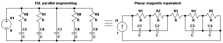
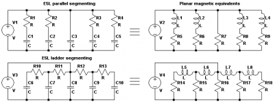
Segmented planar magnetic speaker is doable. I finished such a construction recently. I connected the aluminum segments electrically in series and segmenting filter was done with parallel capacitors.
If you think of current drive, this provides the same electrical response as ESL parallel segmenting RC filter. Response with voltage drive is different but it does not affect the segmenting. A series L-C-R filter was used to correct the overall response.
I used 12 um polyester and 27 um aluminum which is rather heavy duty. I got barely enough high frequency output and impedance minimum is low. Your 13 um aluminum should be less problematic.
Maybe you can get more info from my web page. It's in Finnish, so try a translator.
Magnetostaattiset kaiuttimet
RL structure (inductor in series with segments) was considered but it seemed impractical:
- Series configuration: each segment would need a bypass-path for high frequencies (capacitor and/or resistor).
- Parallel configuration: total impedance would be very low. However, this would make direct counterparts to ESL parallel and ladder structures. It could be doable with very thin aluminum strips or an impedance transformer.
Attachments
Many thanks Pollo, and that's a very nicely constructed project you have there! I'm using a vertical array of open backed woofers for the bass so I'm only looking to use the planamagnetc driver down to 300-500 Hz. I was hoping for good sensitivity with the NdFeB magnets so your finding concerns me a bit. Perhaps the thinner foil will help.
Do you have any directivity measurements you could share? I think they'd be on the topic of the original thread and the comparison with ESLs might be of interest.
Thanks again
Few
Do you have any directivity measurements you could share? I think they'd be on the topic of the original thread and the comparison with ESLs might be of interest.
Thanks again
Few
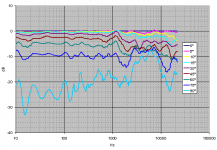
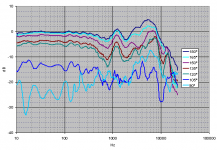
The widths of segments are 67 - 43 - 17 - 43 - 67 mm, and the total width of the speaker is 360 mm. Low-pass corner frequencies are 730 and 370 Hz for 43 and 67 mm segments respectively. There may be still some room to optimize the widths, frequencies and number of bands.
Frequency response was measured in an anechoic chamber from 0 (front) to 90 (side) to 180 degrees (back). We are not interested in the front response here because it can be equalized freely. The curves are normalized relative to the front response to demonstrate the directivity more clearly. Some smoothing was applied.
The attached pictures shows the horizontal directivity in the front and the rear. Radiation pattern is almost a figure-of-eight below 1 kHz. There are some irregularities above 1 kHz, but I have avoided strong beaming at highest frequencies. The rear responses are not as pretty as the front responses. Lower treble is peaking and higher is attenuated, which is caused by mechanical structure (magnets, perforated plate, damping material). ESL would be better in this respect.
The sensitivity was good in the midrange before I added the series filter. I had to attenuate 1.5 kHz up to 17 dB to get the midrange at the same level as bass and treble. Lighter materials should extend the good sensitivity range to higher frequencies.
Attachments
Few, In the link on post 3 I did some simulations showing the effect of dispersion vs Frequency and radiating area width.
When the width equals one wavelength it is typically a figure 8 pattern and as the frequency is lowered it transitions to a circular omni pattern.
In my design I used a doubling of width per each next section of radiating area.
Some use all equal width sections, Which one is better I do not know.
But by using the Segmented ESL simulator it shows that the more the number of smaller sections there is, smoother the field of dispersion becomes is as the frequency is raised.
The center section is driven fullrange and each next section outside of the center is driven with less high frequency's.
You probably all ready knew this but you must keep this in mind when you are configuring your sectional crossover.
I have been thinking about such a system as well.
FWIW
jer
Last edited:
Hi Few
There are three effects that contribute to the horizontal polar response.
Firstly, all dipole radiators have a basic cos(angle) dependence in their response. This gives the figure 8 response geraldfryjr referred to. There’s nothing you can do about this term.
The second factor is determined by the width of the strips. This gives a sin(x)/x function where x=pi.f.width.sin(angle)/c. To minimise phase reversals with increasing angle at high frequencies – say up to 20 kHz, the strips should be less than about 15 mm.
For ESLs, the third factor has to do with the current distribution in the different segments. With the RC transmission line, the polar response also has a term that looks like a second order Butterworth response with angle.
The overall polar response is the product of the three terms. If you keep the strip width small and get the drive current distribution right, then you can get the polar response to be well behaved.
regards
- Status
- This old topic is closed. If you want to reopen this topic, contact a moderator using the "Report Post" button.
- Home
- Loudspeakers
- Planars & Exotics
- Another segmented ESL