HI guys
So now that i'm leaning away from directly driving the MRT of the Full Range. Just too risky! i would like to explore upgrading the components of the transformer box. First off - does anyone have a schematic for the trans box?? I have not taken mine apart but would like to get an idea of how much capacitance exists in the XO. has anyone replaced the caps in theirs?
Also would appreciate hearing from anyone who has replaced the MR transformer. i have heard that one good substitution is to replace the MR trans with one of Paul Speltz Zeroformer. That might be soncially superior to a transformer but i wonder how you go about figuring out what multiplication factor to use on the Speltz and I also wonder whether the stock trans inductance is part of the general crossover structure?
Thanks everyone
--Have you decided upon Xover frequencies and slopes?
--Have you decided upon the final load impedance of each ribbon that the amp drives?
--Will you stay with the original shallow 6db/octave slopes and Xover frequencies?
--Steeper Slopes?
--Different Xover frequencies?
--All passive components?
--Passive + active combined?
It is safe to direct drive the bass panel with an active Xover circuit + KRS 200 channel.
For the midrange you can use the production transformer with active Xover circuit + KRS 200. or-You could wind a new step-up transformer with a 1-ohm load to gain improved dynamics without the risks of direct drive DC/THUMP damage. or-You could re-wind your present Xformer core with a 1-ohm primary.
For the tweeter, only because it is pure resistive impedance:
Active+passive mix 6Khz example: For the tweeter you could put a single series capacitor to create a 6db/octave slope at say 6000_Hz, and use your active Xover box to increase the slope to 18db or 24db or ??db. The series capacitor will protect the tweeter ribbon from DC and most low frequency on/off THUMPS
C = 1 / (2*PI*R*Freq)
1.2 ohms tweeter 6db/octave at 6Khz == 22.1 µF + Active Xover slope.
THE OTHER option for the tweeter is to put a much higher value series capacitor (say 80uf) which will easily pass the 6Khz+ signal, in order to protect the ribbon from AMP DC/THUMPS, and then get the full ??db/octave slope from the active Xover. The capacitor just blocks DC and low frequency crappp.
=============
(Would you have the patience to unplug and take the top cover off one Krell KRS 200 and snap a few photos? Look around the input circuit area for a discrete DC servo circuit. Probably uses large yellow 2uF - 4uF integrator capacitors. Probably uses a dual JFET package. Probably has a small adjustment POT. If you have a very soft bristle brush and a vacuum cleaner you could do a light dust-Bunny cleaning to justify the time. )
Thanks LS
your insight and knowlege are greatly appreciated.
For now lets just go with the tri-amp option. will use 3-way active line level filtering. Can vary the XO points and slopes at will but probably start with stock 6 db slopes and 400/6000 XO points (btw does MR extend far enough to support 6000 XO point with 6db slope?).
MR will need transformer to raise impednace to approx 1 ohm (any idea what specs should be for this?).
Not sure about the TW: its already close to 1 ohm so dont necessarily need a transformer other than as a DC blocker. Sonically wouldnt a good transformer sound better than 80 uF, or so, of capacitance??
other than the need for a lot of cables i like this option over upgrading the stock transformer box, or at least i think i do")
your insight and knowlege are greatly appreciated.
For now lets just go with the tri-amp option. will use 3-way active line level filtering. Can vary the XO points and slopes at will but probably start with stock 6 db slopes and 400/6000 XO points (btw does MR extend far enough to support 6000 XO point with 6db slope?).
MR will need transformer to raise impednace to approx 1 ohm (any idea what specs should be for this?).
Not sure about the TW: its already close to 1 ohm so dont necessarily need a transformer other than as a DC blocker. Sonically wouldnt a good transformer sound better than 80 uF, or so, of capacitance??
other than the need for a lot of cables i like this option over upgrading the stock transformer box, or at least i think i do
Hi LS
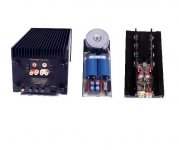
attached are two shots of the KRS 200 with top removed. Hope they are of some value
I am still wrestling with whether to tri-amp and go along lines you suggest or just stick with the stock transformer box configuration and replace caps/resistors. as you have already suggested elsewhere it all boils down to the MR ribbon.
If i tri-amp i can use custom transformer configured to bring impedance up to 1.0 ohm OR use a Speltz Autoformer in series with capacitors to block dc. i have inquires out to EMIA, Tribute and Electra-Print on the custom transformer and only Electra-print has responded saying he needs $250 engineering charge to figure out the best configuration. So i am wondering if the custom transformer route will be less straight forward than i thought?
Using the Speltz autoformer is nice as i can play with step-up ratios but it will require DC blocking capacitors. Unlike the TW ribbon the XO point for the MR pretty much will require capcitors to be part of the filter if i use Speltz auto former. So would probably use a capacitance that produces 6 db slope and i can then add further slope with active line level crossover. But what sounds 'better' : custom transformer or autoformer in series with caps??
if i stay with stock configuration i should at least replace the caps. But this gets expensive if you want really good caps. Plus would need to build new box to contain them.
i think the custom transformer is probably the best option IF i can get the appropriate build specs figured out. any ideas?
lastly i have a question: if i use higher order slopes of either 12 or 18 db do i need to reverse the polarity on the MR ribbon?
Guess thats enough brain damage for now. All comments/help greatly appreciated
Thanks
Attachments
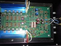
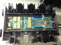
Thank you for taking the time and effort to post pictures of the internals of your KRS 200 amp. The circuits and PCB layout appear very clean and well thought out when compared to my antique KSA250. Attaching the output transistors directly to the BIG heatsink is much more efficient than the indirect double-interface on the KSA250.
I was hoping to see an obvious trim pot for your DC Servo circuit, but I could not clearly identify it on the main PCB picture. If one of your KRS amp channels has <1.5mV DC offset, it seems logical that all of your amp channels should be capable of approaching this low level. This might change your final plans.
You have great amps and active Xover equipment. Perhaps it would be worth the effort to tri-amp with the current interface box and select desirable Xover frequencies and slopes before you decide upon purchasing new transformers and capacitors. e.g. a 24db/octave Xover at 200Hz for the midrange ribbon injects less bass energy than a 6db/octave at 400Hz, and also put less directional information on the large area bass panel. I would not use an "autotransformer" for the midrange ribbon because it does not isolate DC junk. You could live with the current midrange transformer. Rewind the current midrange transformer primary for 1-ohm impedence. Wind a new 1-ohm transformer. Test your love for 6db/octave vs. steeper slopes!
TEST: TEST:
1) It is safe to direct drive the 2.2 ohm bass panel. Use active Xover and KRS 200 channel. Select Xover freq and slope.
2) Using the 4-ohm Apogee transformer, it is safe to direct drive the midrange ribbon. Use active Xover and KRS 200 channel. Select Xover freq and slope.
3) Using the "standard" Apogee tweeter box with a 4-ohm, 6db/octave, 4000Hz Xover, it is safe to direct drive the tweeter ribbon with a active Xover and good solid state amp. Select slope. A single capacitor to isolate DC might be all that is required for the tweeter, plus active Xover to increase slope. Purchase/cobble a different value tweeter DC-blocking capacitor for any frequency other than 4000Hz standard box.
C = 1 / (2*PI*R*Freq)
1.2 ohms tweeter 6db/octave
==========
bass - 2.2 ohms Direct Drive
MR - .5-.6 ohms Transformer to 1-ohm for isolation, or direct drive with 1.5 ohm series resistor if DC offset <1.5mv.
TW - 1.2 ohms (option: series resistor to 2 ohms.. then) Add series capacitor for DC protection, then direct drive.
Attachments
Thank you LS
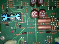
ive attached a close up of the back of the driver boards. i can only find two small components that have a trim feature. you can see the in this picture.
Quick question:
in your response you noted in Test #2 that i could use the stock 4 ohm transformer to interface between amp/active XO and MR ribbon. this is a good idea i think. But I assume you mean that i remove the 4 ohm transformer from the stock transformer box and just connect it directly to amp and MR ribbon. is this correct? or is there a way to do this and still leave the 4 ohm transformer in the original box
i already am direct driving the bass ribbon with one pair of KRS 200.
direct drive the TW should be easy - can either just use series capacitor to block dc (Clayton s40 amp should handle the 1 ohm load ok) or add 1 ohm resistor in series with the caps to raise impedance. TW is not an issue, its only the MR
Attachments
Attaching the output transistors directly to the BIG heatsink is much more efficient than the indirect double-interface on the KSA250.
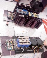
Funny you would say this, i had a pr of the KMA 160, But after haveing the KSA150 an 250 that if biaset right most are way off....thay can be sweet like big tube amps... bias off an sound at best like chep Sand amps....but the KMA 160 did not even sound right even when biaset right....
Dan D. said thay changed the Heat sinks type ASAP ...from the one used on the KRS 200 an my 160s...because thay can Ring like a bells....the KSA 150-250 heatsinks type were there the best sounging sinks.... but were big $$$ this is just my finding after owen minny Krell amps an preamps an D/As, Crossover for the B&W 801 an the Apogees, .........
But on the Apogee That you are trying to run ...have you just ran them with the stock crossover??...
I had the Duettas on the best crossover i could find the Krell KBX an in the end found with one amp an the stock crossover i got better sound.....
thanks for any an all info on Apogees
Last edited:
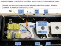
I assume you mean that i remove the 4 ohm transformer from the stock transformer box and just connect it directly to amp and MR ribbon. is this correct? or is there a way to do this and still leave the 4 ohm transformer in the original box)
I believe most Full Range interface boxes provide additional terminals on the amplifier side in order to support the option to direct drive each of the three ribbons with Tri-Amp. From the Factory, it was common to have the mid_transformer wires PLUS tweeter Xover passive component wires connected to the same amp terminals for Bi-Amp. If you move the two tweeter wires onto the unused terminals on the amp side you can use the box for tri-amping.
You could always drill extra holes for these amp terminals if your interface box only supports Bi-Amp connection.
If you ever want to experiment with re-wiring your current midrange transformer you would need to:
1) calculate the new turns ratio for the input primary (easy.. just re-measure resistance of mid ribbon as a double check before calcs.)
2) unwind the thin primary wire. NOTE how it is wound. Single-wire? Double-Wire(2x fold)? Tri-Wire(3x fold)? 2x and 3x folding is sometimes used to reduce inductance, but this is less critical with a modest number of turns.
3) Purchase correct gauge wire for: length = 1 ohm
OR you could purchase a new core and have 2 transformers to experiment with. Study the simple, modest turns on your mid transformer to gain confidence.
Attachments
direct drive the TW should be easy - can either just use series capacitor to block dc (Clayton s40 amp should handle the 1 ohm load ok)
I do not recognize any of the pictured circuits as a DC servo. I just do not see the large non-polarized caps used for DC integrators that I normally use. Perphaps another reader will know how to adjust the DC offset level. Your DC direct ribbon experiments prove how important a 1-2mv DC offset is for optimal direct drive safety. I would not personally put a DC servo on the RELAY PCB on the rear panel, but Krell engineers might have selected that location because of access to the output signal.
Your Clayton S40 amp only has 4 output transistors per channel. Your owner's manual would likely spec the maximum continuous power into 1.2ohms. My DIY ribbon amps have 20 * 180-watt outputs/channel for a 1 ohm ribbon. You may end up using the Apogee 4-ohm tweeter interface to avoid damaging the Clayton S40.
==========
Let’s suppose you want to experiment with the reduced driver overlap of a 24db/octave acoustic slope.
FOR MID-TWEET… you use the standard Apogee Xover box wired for Tri-Amp which has a 4-ohm impedance that the Clayton S40 will like, and the Apogee capacitor-based passive 6db/octave slope at 4000hz. You program your active Xover for 18db/octave at 4000Hz and together you have a 24db/octave slope acoustic Xover. This combination is NOT EXACTLY the Linkwitz Riley ganged equation. For the midrange ribbon Xover, you use the 4-ohm transformer connected to the Krell KRS200, and program your active xover to 4000Hz at 24db/octave to match the tweeter. Again, maybe not a perfect match to the tweeter.
FOR BASS-MID: You program your bass active Xover for 24db/octave at 200Hz for both the bass and midrange. A 24db/octave Xover at 200Hz will put less bass energy on the delicate midrange ribbon than the original 6db/octave crossover at 400Hz. Direct drive the 1.8 ohm bass panel. Use the 4-ohm transformer for the midrange ribbon, adjust Xover gain for equal SPLs.
One Xover experiment completed! No amp destruction! No ribbon destruction!
Attachments
Last edited:
thank you LS
as always your knowledge and insight are most appreciated! I think we are getting to the point where i am well armed to find the best combination of amps and crossover components.
I will keep everyone informed of my progress!
PS - will ask Krell where and how the dc offset is adjusted as well as the bias. one piece of good news - i measured all the caps on the driver boards and they are all within 5%.
LS-
have you replaced the caps in your transformer box? if so i would be interested in what brand cap you used to replace them with. If i just stick with bi-amping the logical upgrade, other than possibly re-winding the MR transformer to 1 ohm would be to upgrade the stock caps and resistors. Just wondering what your experience has been with upgrades?
Thanks again LS
PS - even in their stock form the sound from the FR with the KRS is really lovely.
LS-
have you replaced the caps in your transformer box?
I have not replaced the standard capacitors. They are now about 20 years old, and I do not hear any distortion. Good time to measure them for deterioration.
"Out of sight, out of mind"..
Have you experimented with a steeper Xover slope between the bass panel and mid-tweet Xover? LR4 24db/octave slope at 200Hz should be a safe, simple experiment with your active Xover hardware. An experiment like this might help your future decisions for mid, tweet Xover slopes and frequencies.
- Status
- This old topic is closed. If you want to reopen this topic, contact a moderator using the "Report Post" button.
- Home
- Loudspeakers
- Planars & Exotics
- Rebuilding Transformer box for Apogee Full Range