Then the depth of the wave guide should match the 15" - depth from front of driver (15") to where the voice coil / dust cap are mounted. My 15" cones are 100 mm deep....
But shouldn´t the wave guide depth start at where the AMT´s area is equal to the 15"´s area and not at the dust cap?
If you use a waveguide instead of EQ you will improve the fidelity as the distortion will be much lower. And the directivity and soundstage improves also...
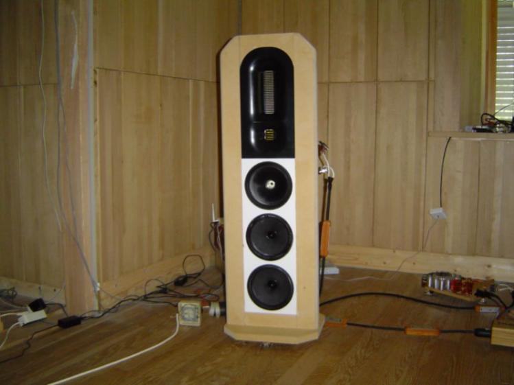
Picture shows the first prototype with AMT "midrange" and AMT "super tweeter" in a CNCed Corian waveguide, and three 8" drivers in a combined CNCed Corian baffle / basket..
hi Raymond
your prototype amt speakers looks amazing. How does it perform ? where do you cross the amt to the cone woofers ? Will you develope a bass amt later on ?
Angelo
But shouldn´t the wave guide depth start at where the AMT´s area is equal to the 15"´s area and not at the dust cap?
For a starter 50 mm should be easy for you to implement.
hi Raymond
your prototype amt speakers looks amazing. How does it perform ? where do you cross the amt to the cone woofers ? Will you develope a bass amt later on ?
Angelo
300 or 500Hz (6dB/oct series filter). Bass AMT diaphragms and parts was developed and made more than three years ago - but never assembled.. Since then a lot of new products / technologies have been researched, developed and prototypes made.. Production, marketing and sales are not my "cup of tea" and time and cash then only allows for prototypes and pre-production items for my own use...
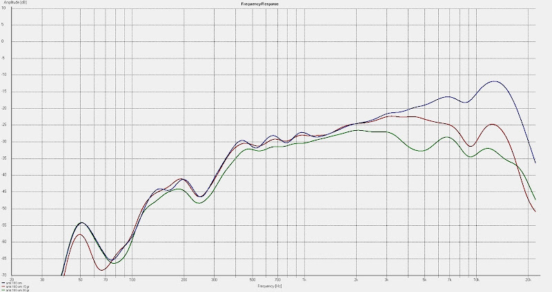
Frequency plots at 1 m. 0, 15 and 30 degrees.
This membrane with 7 um doesn´t go quite as low as the 10 um membrane.
With wave guide this will change slightly and I expect a 5 to 10 degree placement (with wave guide) will give very good results..
Filtered at 200 - 250Hz and you will have -3dB at 350 - 400Hz...
Last edited:
300 or 500Hz (6dB/oct series filter). Bass AMT diaphragms and parts was developed and made more than three years ago - but never assembled.. Since then a lot of new products / technologies have been researched, developed and prototypes made.. Production, marketing and sales are not my "cup of tea" and time and cash then only allows for prototypes and pre-production items for my own use...
hi Raymond
are your plans to make progress with the bass amt this year ? A fullrange amt speaker will be a major evolution, if not revolution, in high-end audio......
")
hi Raymond
are your plans to make progress with the bass amt this year ? A fullrange amt speaker will be a major evolution, if not revolution, in high-end audio......
Plans = yes, time and cash = ?
Wave guide measurements
So I carved out a rudimentary wave guide out of two layers of 50 mm XPS sheets:

Measured the AMT at 100 cm distance at 0, 15 and 30 degrees:
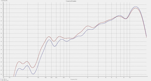
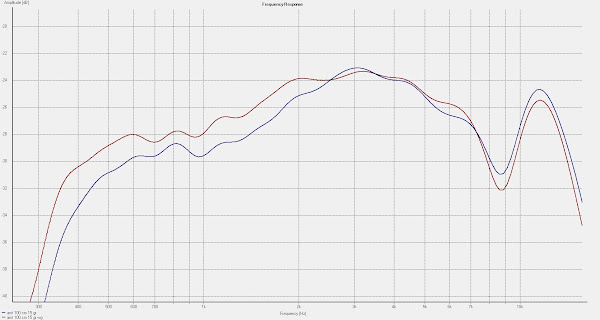

Note that the screenshots doesn´t have the same scale.
A couple of dBs higher output from 2500 Hz and downwards.
So with a better wave guide and membranes with 10 um aluminium I should be able to go even lower.
What to do with the suckout at 8500 Hz and the 13 kHz roll-off?
So I carved out a rudimentary wave guide out of two layers of 50 mm XPS sheets:
Measured the AMT at 100 cm distance at 0, 15 and 30 degrees:
Note that the screenshots doesn´t have the same scale.
A couple of dBs higher output from 2500 Hz and downwards.
So with a better wave guide and membranes with 10 um aluminium I should be able to go even lower.
What to do with the suckout at 8500 Hz and the 13 kHz roll-off?
Last edited:
So I carved out a rudimentary wave guide out of two layers of 50 mm XPS sheets:
A couple of dBs higher output from 2500 Hz and downwards.
So with a better wave guide and membranes with 10 um aluminium I should be able to go even lower.
What to do with the suckout at 8500 Hz and the 13 kHz roll-off?
By using a steel wire shaped to the wanted wave guide shape - then running DC current through it so it just get hot enough to cut the XPS (like a hot knife in butter) you can make wave guides with nearly perfect surface finish..
You will get more than 2 dB extension with a better wave guide shape.
The Monacor WG300 wave guide shape here shows a basic shape you can have in mind when you figure out your own ideal shape http://www.monacor.de/en/products/speaker-technology/hifi-tweeters/wg-300/
Expect the 8.5kHz and 13kHz problems will be gone when the wave guide (shape) are finished, and the outer perimeter of the wave guide are rounded off. You will find the causes for 8.5kHz and 13kHz issues if you calculate the distances in the current "prototype".
In my first wave guide I had similar issues before the shape was perfected...
I have had a CNC tool made with the wave guide shape that match my midrange AMT, tweeter AMT and 8" metrics.
Last edited:


I have build a horn this way:
![URL]](/community/proxy.php?image=http%3A%2F%2F%5BURL%3Dhttp%3A%2F%2Fimg51.imageshack.us%2Fi%2Fhorn11.jpg%2F%5D%5BIMGDEAD%5Dhttp%3A%2F%2Fimg51.imageshack.us%2Fimg51%2F8724%2Fhorn11.jpg%5B%2FIMGDEAD%5D%5B%2FURL%5D&hash=5ef3289b4a3f72d3db5fa41f7b9ff772)
![URL]](/community/proxy.php?image=http%3A%2F%2F%5BURL%3Dhttp%3A%2F%2Fimg534.imageshack.us%2Fi%2Famt007.jpg%2F%5D%5BIMGDEAD%5Dhttp%3A%2F%2Fimg534.imageshack.us%2Fimg534%2F1913%2Famt007.jpg%5B%2FIMGDEAD%5D%5B%2FURL%5D&hash=b8d4ba2519d3f0a53faf31a58aecf68a)
I used plates for dampning of resonanses in cars:Smeltefolie, bitumen 4 stk. - Biltema
![URL]](/community/proxy.php?image=http%3A%2F%2F%5BURL%3Dhttp%3A%2F%2Fimg21.imageshack.us%2Fi%2Fhorn12.jpg%2F%5D%5BIMGDEAD%5Dhttp%3A%2F%2Fimg21.imageshack.us%2Fimg21%2F4268%2Fhorn12.jpg%5B%2FIMGDEAD%5D%5B%2FURL%5D&hash=b044f319e93f4ac68655dca49e1d81d7)
I can take more Pictures as the bitumen plates are selfadhesive.
I have not calculated the curves .
Bernt
An externally hosted image should be here but it was not working when we last tested it.
I used plates for dampning of resonanses in cars:Smeltefolie, bitumen 4 stk. - Biltema
I can take more Pictures as the bitumen plates are selfadhesive.
I have not calculated the curves .
Bernt
Last edited:
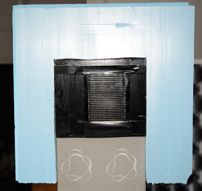
Grid measurement
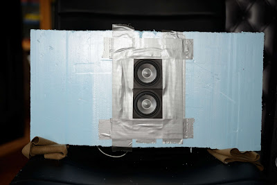
The two E60 from above was the drivers when this simple test was made:
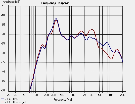
how does the grid affect the frequency response.
The 400 resonans is probably because the measurment where made with the baffle a couple of inches from the floor. It would have been hard to get the heavy grid to stay in place in front of the baffle otherwise.
Now, the E60 are not AMTs, but this should give a hint what acoustic effect the grid has. I see no significant correlation between this measurement and that of the real AMT.
But of course should one want the two curves above to be the more or less same.
Removing every other bar affects the field to much, but perhaps there´s a reasonable compromise between field strenght and sound affection somewhere inbetween.
Back to FEMM and then make a new dummy grid...
The two E60 from above was the drivers when this simple test was made:
how does the grid affect the frequency response.
The 400 resonans is probably because the measurment where made with the baffle a couple of inches from the floor. It would have been hard to get the heavy grid to stay in place in front of the baffle otherwise.
Now, the E60 are not AMTs, but this should give a hint what acoustic effect the grid has. I see no significant correlation between this measurement and that of the real AMT.
But of course should one want the two curves above to be the more or less same.
Removing every other bar affects the field to much, but perhaps there´s a reasonable compromise between field strenght and sound affection somewhere inbetween.
Back to FEMM and then make a new dummy grid...
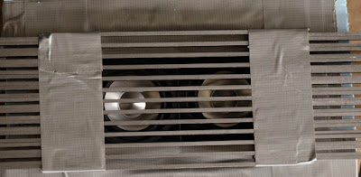
Sparse grid measurement
With a more sparse grid; the iron bars are 6 mm apart:
Simulated the inverted motor with FEMM:
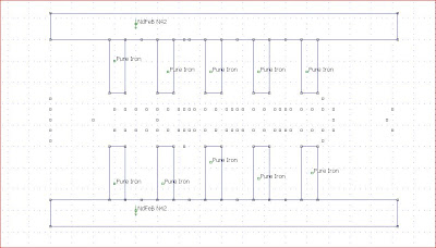
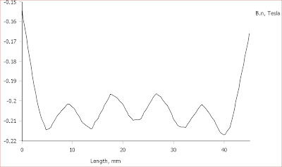
It gave a reasonable even field:
Real measurement with E60s:
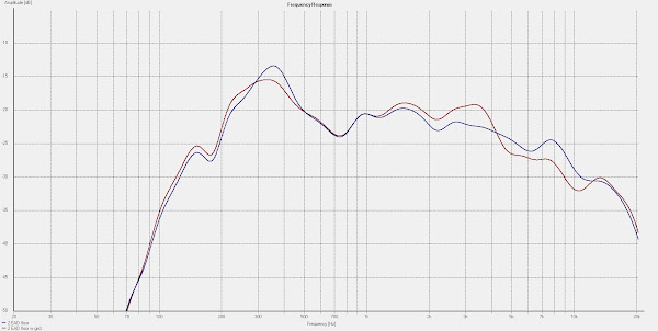
The same charasteristics as for 3 mm spacing but half the effect, I would say.
So is it worth changing the motor for, especially when the field is not as even as with 3 mm spacing?
With a more sparse grid; the iron bars are 6 mm apart:
Simulated the inverted motor with FEMM:
It gave a reasonable even field:
Real measurement with E60s:
The same charasteristics as for 3 mm spacing but half the effect, I would say.
So is it worth changing the motor for, especially when the field is not as even as with 3 mm spacing?
- Status
- This old topic is closed. If you want to reopen this topic, contact a moderator using the "Report Post" button.
- Home
- Loudspeakers
- Planars & Exotics
- Yet another DIY AMT