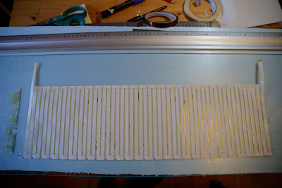
Some pictures from the manufactoring of the new membranes with 10 um aliminium and peelable paper back.
This material is much easier to cut as the paper has less friction.It is much easier to
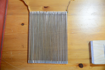
Cut and taped:

Cutout raw membrane:

Previous membrane had attached terminals, they were not reliable and caused heat. Now the aluminium itself extends as terminals. A piece of kapton tape supports the fragile bare aluminium.
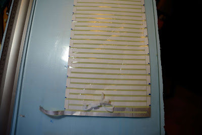
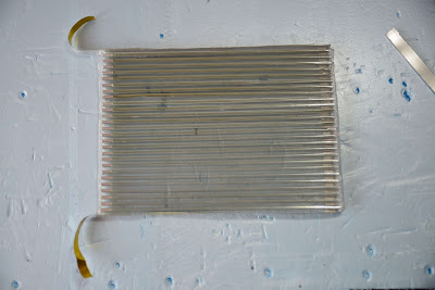
Flip the membrane and peel of the paper:
This material is much easier to cut as the paper has less friction.It is much easier to
Cut and taped:
Cutout raw membrane:
Previous membrane had attached terminals, they were not reliable and caused heat. Now the aluminium itself extends as terminals. A piece of kapton tape supports the fragile bare aluminium.
Flip the membrane and peel of the paper:


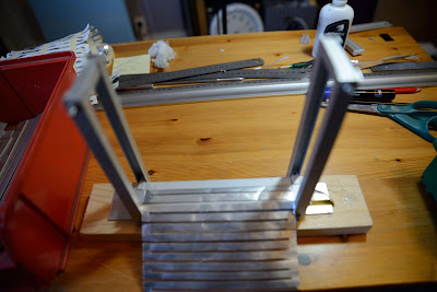


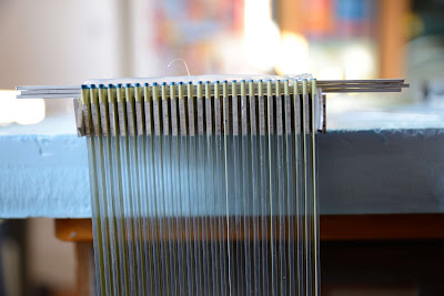
The top and the bottom will be accessible, but what about the sides?
Trying with a 1 mm alu stick taped outside the first and last folds.

Again some Kapton tape, this time to attach the sticks to the membrane.
It doesn´t work that well, the 1 mm alu stick is not stiff enough.
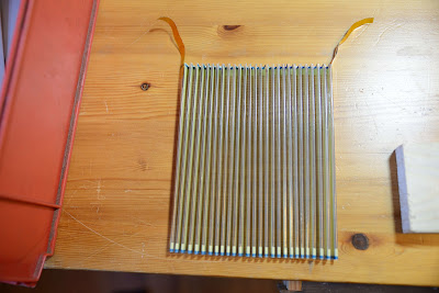
I´ll try with a jig saw blade, it is stiffer and would also adhere to the magnetes.
Trying with a 1 mm alu stick taped outside the first and last folds.
Again some Kapton tape, this time to attach the sticks to the membrane.
It doesn´t work that well, the 1 mm alu stick is not stiff enough.
I´ll try with a jig saw blade, it is stiffer and would also adhere to the magnetes.

Did som initial listenening, great sound stage and all, but something was wrong.
Swept with Holm, almost the same characteristics as for the former membrane: 200 Hz till 20 kHz, 6 dB/oktavs increase after efter 2-3 kHz, a dip at vid 15 kHz.
I will try the thin foil (7 um alu) as well with this building practice to see if there´s any different response in the lows.
That the response is only from 200 Hz is really not a problem, my OBs matches that well. In fact, I could probably have no filter at all for the AMTs. Well, apart from some DC-protection then.
I will try some baffles anyway, but I suspect that they will mess up the sound stage as usual.
Continued with REW in order to do same fault finding, discovered vibrations at 230 Hz and 460 Hz. They didn´t match any dimensions at first but several halvings of the wavelenght revealed a standing wave of 18 cm corresponding to the pipe I have made when I sealed the top and the bottom .
.
Got rid of the tape, got rid of the vibrations .
.
Had another vibration at 510 Hz, the glue had no contact with the steel at one end. Easily corrected as well: Happiness is a warm glue gun!
NOW IT IS REALLY PLAYING!!
Swept with Holm, almost the same characteristics as for the former membrane: 200 Hz till 20 kHz, 6 dB/oktavs increase after efter 2-3 kHz, a dip at vid 15 kHz.
I will try the thin foil (7 um alu) as well with this building practice to see if there´s any different response in the lows.
That the response is only from 200 Hz is really not a problem, my OBs matches that well. In fact, I could probably have no filter at all for the AMTs. Well, apart from some DC-protection then.
I will try some baffles anyway, but I suspect that they will mess up the sound stage as usual.
a misguided attempt
Continued with REW in order to do same fault finding, discovered vibrations at 230 Hz and 460 Hz. They didn´t match any dimensions at first but several halvings of the wavelenght revealed a standing wave of 18 cm corresponding to the pipe I have made when I sealed the top and the bottom
.Got rid of the tape, got rid of the vibrations
.Had another vibration at 510 Hz, the glue had no contact with the steel at one end. Easily corrected as well: Happiness is a warm glue gun!
NOW IT IS REALLY PLAYING!!
I don´t think that I can have more percentage alu and besides the efficiency is good enough as it is.You could cower more surface with alu,it might reduce resonances.Weight on a normal diaphragm lowers resonance and eficiensy.
What about low frequency response?
I don´t know in absolute numbers as I have no calibrated microphone or SPL-meter. But I´d say they are 3 to 6 dB better than my line arrays.How effective is your Amt?
It is 7 mm alu with 3 mm gaps.How wide are the traces without alu?
Yes, and I will post some soon (just gonna make just one more adjustment ...)Do you know how to attach measurements ?
I dont have ideas for improvment yet.
If you want a calibrated mic, Mini DSP have one,and you can buy it from Norway:
AVshop.no / minidsp UMIK-1 USB målemikrofon
It is able to measure SPL with REW.
More details here:http://www.minidsp.com/images/documents/Product%20Brief%20-%20Umik.pdf
Bernt
If you want a calibrated mic, Mini DSP have one,and you can buy it from Norway:
AVshop.no / minidsp UMIK-1 USB målemikrofon
It is able to measure SPL with REW.
More details here:http://www.minidsp.com/images/documents/Product%20Brief%20-%20Umik.pdf
Bernt
Last edited:
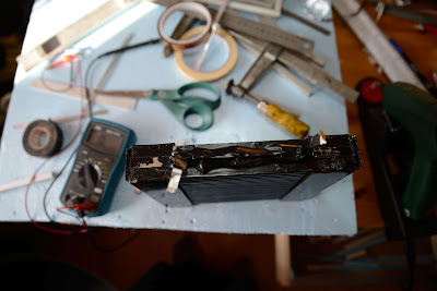
Still problem with resonances.
These are only due to the cavity´s dimensions, it´s a whole lot of air being compressed and decompressed.
The frequencies I´ve noticed to produce unwanted vibrations are around 230, 460 and 510 Hz.
The cavity is 160 high and 120 mm broad. The iron rods in front and back of the element is 10 mm times 3 mm and the gap between them is also 3 mm.
I´ve discovered that putting my hand in front or at the back of the element reduces the vibrations, maybe som cloth behind the element can be a remedy.
For now the membrane will be glue completely at the top and the bottom; the vibrations are hardly noticeable during listening.
But of course, knowing that they are there is annoying enough to hinder the listenening to be completely relaxed.
Hi Solhaga,
Some AMT´s have a thin piece of felt placed at the back of the AMT to cope with unwanted movements of the diaphragm.
As you have discovered, this might be worth trying-out. If possible, you could try with, say, 2-5 pieces of felt with different thickness.
It´s cheap and worth trying. Hopefully it will bring you closer to the finished DIY AMT.
Karsten

The felt is dampening the unwanted vibrations but not enough.
It is the fastening of the membrane on the sides that are the main problem.
The first and last pleats doesn´t adhere to the motor enough.
If I could get some glue between the iron rods the vibrations will probably get away.
It is the fastening of the membrane on the sides that are the main problem.
The first and last pleats doesn´t adhere to the motor enough.
If I could get some glue between the iron rods the vibrations will probably get away.
Bummer
Not coming to terms with the unwanted vibrations made me re-evaluate the membrane.
Should I make in slimmer, perhaps 6 mm in the 10 mm gap?
Should I make the folds further apart, perhaps 4 mm between the pleats?
Then I came to think of the current in the magnetic field thus producing the forces that makes the pleats compress and de-compress.
What about the forces on the part of the aluminium conductor that are not supposed to produce any sound?
At any given moment, that is direction of the current, every other pleat moves left and the other right thus producing the every other fold to either compress or de-compress the air, but the horizontal conductors at the top and the bottom moves in the same direction, let´s say down. When the current switches the horizontal conductors at the top and the bottom move in the other direction, that is up.
The membrane is being moved up and down with the music.
That shouldn´t do any harm if it wasn´t for the fact that the membrane is fixed at the top and the bottom.
So either the membrane should be free to move up and down, but that is difficult to accomplish as the membrane needs to be fixed so it doesn´t touch the iron rods, or the horizontal conductors must be out of the magnetic field.
So I need a wider membrane and thus a wider film or make some other arrangements to get the horizontal conductors out of the magnetic field.
Back to the drawing board...
(Please correct me if I am wrong!)
- Status
- This old topic is closed. If you want to reopen this topic, contact a moderator using the "Report Post" button.
- Home
- Loudspeakers
- Planars & Exotics
- Yet another DIY AMT