This leads to something that has puzzled me for 50 years: where are the electret speakers?
An electret is a material that can retain a charge "permanently".
Basically the electrostatic equivalent of a permanent magnet.
So, an electret speaker or microphone can be thought of as an ESL that doesn't require a HV bias supply.
It's main use has been with microphones, but it has been used with some success in headphones.
Bolserst - thanks.
I think Stax made ESL headphones both ways.
If excellent for mics, why not speakers? Why not DIY?
Ben
Pressure gradient is difference in pressure, so how can we say "there is no pressure gradient" when there is sound in air??
When wavelength is small compared to glass size(which is true for all but the lowest frequency) different parts of glass will be hit at different times from typical sound sources so phase is not the same across the area.
I do not really get what do you mean by "strictly pressure operation" under these conditions ?
It would take me some time to describe it, so a quick google search shows this article, which explains it quite nicely (the first part):
Understanding & Using Directional Microphones
Also at 20 kHz 4-5 mm thick glass looks like a very hard wall with thickness equal to about a quarter the wave length(compare this to ~1.7meter@50Hz).
First, I am not sure we are talking the same thing. I am not trying to convince that such system would cover up to 20KHz (in this case microphone manufacturers would start making mics out of window glass). What I was saying is the glass window will have (in principle) flat response and have enough bandwidth for intelligibility of human speech.
Hello Marik,
Thanks for sharing your knowledge on ribbon microphones. I have no experience with them, but your description of the path length limitation makes sense. I have experimented with using small ESLs (1"x1" up to 3"x3") as microphones and the top end roll off was the same for all sizes if the diaphragm thickness and % open area of the stators was the same. Perhaps the reason for the difference in behavior is that the ribbon is mass controlled so the sound wave takes the path of least resistance and moves/diffracts around the ribbon-magnet structure and develops the delta pressure to move the ribbon. The ESL diaphragm doesn't present an obstruction to the sound wave like a mass controlled ribbon so moves with the air motion rather than reacting to a pressure difference due to the sound wave going around it. Thoughts?
As far as the mass controlled system concerned, even if you tune the system in the middle of the bandwidth (majority of the condenser mic capsules), in any case anything above that frequency is mass operated, and below, of course, stiffness operated. To make a flat response we will need to make the system resistance controlled (or EQ it).
It is hard to tell without seeing your ESLs, but I think in your case the stators work as resonators, which dominate the top response. Does it make sense?
Best, M
I think Stax made ESL headphones both ways.
If excellent for mics, why not speakers? Why not DIY?
The spacing between diaphragm and stators is much smaller in headphones and especially condenser microphone capsules, so there is no need for a high polarization voltage. I don't think electret material could be charged to some 6KV required for ESL speakers.
Best, M
It is hard to tell without seeing your ESLs, but I think in your case the stators work as resonators, which dominate the top response. Does it make sense?
Hmmmm....I might be missing something, but I don't think this is the case. If you are familiar with equivalent circuit modeling, the appropriate acoustic model for the stators would be perforated plates which add some resistance and mass in series with the radiation impedance. I don't think there is any stiffness element in the model that would produce a resonance any where in the top couple octaves.
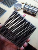
Unfortunately the microphone test panels I was playing around with are still boxed up somewhere due to a recent move. However, attached is a pic to give you an idea of what the stators look like. Large holes in thin metal to minimize added acoustic mass.
If interested, I can post some measurements later this month when I locate them.
Attachments
Last edited:
bolserts,
If I remember correctly most perforated screens such as you are showing have about a 50% open to closed surface area. You would think that would be a lumped impedance in your calculations when doing your modeling? Is it a factor or is the impedance low enough to air at the frequencies we are talking about in a mic to leave that factor out?
If I remember correctly most perforated screens such as you are showing have about a 50% open to closed surface area. You would think that would be a lumped impedance in your calculations when doing your modeling? Is it a factor or is the impedance low enough to air at the frequencies we are talking about in a mic to leave that factor out?
If you are familiar with equivalent circuit modeling, the appropriate acoustic model for the stators would be perforated plates which add some resistance and mass in series with the radiation impedance. I don't think there is any stiffness element in the model that would produce a resonance any where in the top couple octaves.
We also have an equivalent inductance of the opening aperture (holes in the stators), and equivalent capacitance of the air trapped in the chamber formed between stators and diaphragm. The resulting resonant frequency=1/2pi x √LC
Best, M
As best I could tell, the main lumped impedance contribution from the stators is a small inductor(ie mass).bolserts,
If I remember correctly most perforated screens such as you are showing have about a 50% open to closed surface area. You would think that would be a lumped impedance in your calculations when doing your modeling? Is it a factor or is the impedance low enough to air at the frequencies we are talking about in a mic to leave that factor out?
Once you start using diaphragms thinner than 1/4mil(6uM) it starts to to dominate the roll-off behavior.
We also have an equivalent inductance of the opening aperture (holes in the stators), and equivalent capacitance of the air trapped in the chamber formed between stators and diaphragm. The resulting resonant frequency=1/2pi x √LC
Understood, the stator holes act like little slugs of mass(inductance) and their contribution can be quantified using peforated plate formulas in Beranek. As far as the idea of the stator and diaphragm forming a chamber that would have stiffness the slugs of air could resonate with in the top octave...I'm having a hard time thinking that is the case. I'd be more inclined to think any stiffness would just be included as part of the capacitor modeling the diaphragm stiffness due to tenstion. This resonates with the sum of the lumped masses(inductance) which include diaphragm mass, reactive part of radiation impedance, and the stator holes.
But, it is easy to test if there is a resonance in the top octave. We should see the phase wrap if it passes thru a resonance. I don't recall seeing this in any of my measurements, but I wasn't exactly looking for it either.
Question...if this was the case, would you expect to see a similar resonance in the top end of all ESL speakers? I'm 99% sure this is not the case for ESL speakers where the diaphragm is the driving force rather than the air motion thru the stators. I've been surprised before by the difference in behavior when a transducer is used as a microphone vs a speaker, so keeping an open mind...it's the only way to learn
")
We also have an equivalent inductance of the opening aperture (holes in the stators), and equivalent capacitance of the air trapped in the chamber formed between stators and diaphragm. The resulting resonant frequency=1/2pi x √LC
Best, M
I am not sure if this effect could occur in audio frequencies, but remember some people have reporting problems when stators are too thick compared to hole size. It is reported that stators should be thin enough(in the order of 1 mm) with holes ~>2mm or so. However I have never seen a proof of any kind that negative effects are caused by resonance of air inside cavity and not too high air resistance.
Basically theoretical prediction should be backed up by measurements of some sort availability of which I do not know.
I think modeling these effects theoretically would be insanely difficult as we have gas which behaves like fluid, so not only open area matters, but hole size, spacing between holes, its shape, sharpness of the edge etc etc.
Regards,
Lukas.
Last edited:
Understood, the stator holes act like little slugs of mass(inductance) and their contribution can be quantified using peforated plate formulas in Beranek. As far as the idea of the stator and diaphragm forming a chamber that would have stiffness the slugs of air could resonate with in the top octave...I'm having a hard time thinking that is the case. I'd be more inclined to think any stiffness would just be included as part of the capacitor modeling the diaphragm stiffness due to tenstion. This resonates with the sum of the lumped masses(inductance) which include diaphragm mass, reactive part of radiation impedance, and the stator holes.
Let's make it much simpler--forget all equivalents, just think of it as a cavity resonance. IOW, Hemholtz resonator... just a tiny one, tuned into HF.
But, it is easy to test if there is a resonance in the top octave. We should see the phase wrap if it passes thru a resonance. I don't recall seeing this in any of my measurements, but I wasn't exactly looking for it either.
The peak can also be out of band, but still affect things. All I can say, a pure and symmetrical fig8 system (i.e. single diaphragm with its back completely open and both sides having the same acoustical loading) of 1" and 3" wide (or diameter) cannot have the same top frequency response, unless something else is going on.
Question...if this was the case, would you expect to see a similar resonance in the top end of all ESL speakers? I'm 99% sure this is not the case for ESL speakers where the diaphragm is the driving force rather than the air motion thru the stators. I've been surprised before by the difference in behavior when a transducer is used as a microphone vs a speaker, so keeping an open mind...it's the only way to learn
Indeed, the same transducer as a speaker and as a mic is completely different. For example, say overall 5" wide true ribbon speaker will hardly produce anything below some 400Hz with some kind of authority. Our Samar MF65 ribbon microphone with about 3/4" wide motor has -0.4dB on 20Hz (!!!).
I won't be able to give you any analysis of what difference the stators make. I'd think they do, as any obstacle is... an obstacle, and if anything, has its damping properties--after all, this is customary to put damping circles in front of dome tweeters (look at the ScanSpeak D2904, or Seas 27TAFNC/G). Of course, the easiest and quickest way to know would've been just to measure with and without, but unfortunately, we cannot make the ESL to work without stators
. I am not sure if this effect could occur in audio frequencies, but remember some people have reporting problems when stators are too thick compared to hole size. It is reported that stators should be thin enough(in the order of 1 mm) with holes ~>2mm or so. However I have never seen a proof of any kind that negative effects are caused by resonance of air inside cavity and not too high air resistance.
Basically theoretical prediction should be backed up by measurements of some sort availability of which I do not know.
I think modeling these effects theoretically would be insanely difficult as we have gas which behaves like fluid, so not only open area matters, but hole size, spacing between holes, its shape, sharpness of the edge etc etc.
To put the things quite simply, this kind of resonator system is widely used in the microphone production and many commercial mics do use it for HF extension/correction. To start with, most of ribbon microphones do have it, including Coles 4038, RCA 44, RCA BK5, AEA, Melodium 42A, Oktava ML16, 19, 51, Reslo, etc. etc. etc.
Also, many condenser microphones capsules also have it, Oktava MC219, MC319, many Audio Technica's. Heck!--even venerable WM60/61 also do have it!
Unfortunately, for many reasons I won't be able to publish here development data of our own Samar MF65 ribbon mic to fully illustrate the process of frequency response tuning, but I can assure you, as Viagra salesmen use to say: "It works"
Best regards, M
Last edited:
Hi,
I remember in the past I have tried to measure the effect of perforated sheet of metal by placing it between a cone speaker and microphone. The effect was zero with my measurement devices and open area of sheet around 65%. Perhaps it's not too difficult to test some specific stator design?
Regards,
Lukas.
I am familar with the use of plates placed in front of tweeter domes to produce a cavity resonance to boost/shape the HF response. My first experience(many moons ago) was with the Vifa D25AG and its triangular "precision phase lens". With it response was pretty much flat 20 kHz. Out of curiosity, I clipped it off and response started rolling off above 7kHz!I won't be able to give you any analysis of what difference the stators make. I'd think they do, as any obstacle is... an obstacle, and if anything, has its damping properties--after all, this is customary to put damping circles in front of dome tweeters (look at the ScanSpeak D2904, or Seas 27TAFNC/G).
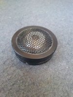
Your mention of tweeter resonator plates reminded me that I have a couple small neo tweeters that use perforated metal to hold a thin plastic resonator plate in front of the dome. I can take measurements:Of course, the easiest and quickest way to know would've been just to measure with and without, but unfortunately, we cannot make the ESL to work without stators
1) With resonantor plate and perforated metal in place (OEM)
2) Resonator plate removed, but perforated metal in place
3) Resonator plate & perforated metal removed.
This should give us an idea how much cavity resonance we might expect from high % open area perforated metal.
I will have access to a B&K 4133 microphone tomorrow night, so will be able to get believeable data up to 40kHz.
Most of the response correction plates I've seen are solid or have very low % open area.To put the things quite simply, this kind of resonator system is widely used in the microphone production and many commercial mics do use it for HF extension/correction.
Just curious, what is the highest % open area correction devise you have seen?
I remember in the past I have tried to measure the effect of perforated sheet of metal by placing it between a cone speaker and microphone. The effect was zero with my measurement devices and open area of sheet around 65%. Perhaps it's not too difficult to test some specific stator design?
The cavity resonance that Marik is describing will probably only be noticeable with the perforated sheet metal very close to the diaphragm, which may not be possible with a woofer. Hopefully the tweeter experiment I described above will give us some insight.
Attachments
Perforated plate Experimental Results
My appologies for the delay on this...too many irons in the fire as of late.
Attachment #1: Shows the tweeter used and 3 different perforated plates tested
Attachment #2: Shows measurements for the "naked" tweeter along with the 3 test plates.
Tweeter was mounted on large board and impulse response windowed to remove edge diffraction contributions.
- Upper plot compares response at 1m on axis for the 4 different setups.
- Lower plot compares the increments for the 3 different test plates.
Results appear to support my experience that thin high % open area perforated plates do not have significant resonant behavior below 20kHz.
Your mention of tweeter resonator plates reminded me that I have a couple small neo tweeters that use perforated metal to hold a thin plastic resonator plate in front of the dome. I can take measurements:
1) With resonantor plate and perforated metal in place (OEM)
2) Resonator plate removed, but perforated metal in place
3) Resonator plate & perforated metal removed.
This should give us an idea how much cavity resonance we might expect from high % open area perforated metal.
My appologies for the delay on this...too many irons in the fire as of late.
Attachment #1: Shows the tweeter used and 3 different perforated plates tested
Attachment #2: Shows measurements for the "naked" tweeter along with the 3 test plates.
Tweeter was mounted on large board and impulse response windowed to remove edge diffraction contributions.
- Upper plot compares response at 1m on axis for the 4 different setups.
- Lower plot compares the increments for the 3 different test plates.
Results appear to support my experience that thin high % open area perforated plates do not have significant resonant behavior below 20kHz.
Attachments
bolserst,
What was your conclusion from the tests? It looks like the tweeter with and without the screen but no phase plug has the flattest and widest bandwidth. Am I interpreting this correctly.
The purpose of the test was to determine if the screen alone would significantly impact response.
My conclusion was that it did not.
I included the other configurations to illustrate the potential cavity resonance behavior that Marik had mentioned in post #30.
When deciding which configuration is best for this particular tweeter you would have to look at off-axis response as well.
When considering off axis, the OEM configuration provided the best/smoothest average response in a +/- 30 deg window.
*** Forget to mention, no data smoothing was used ***
Last edited:
Hi,
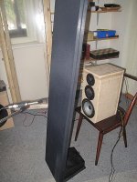
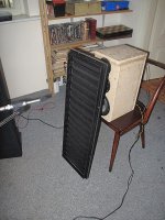
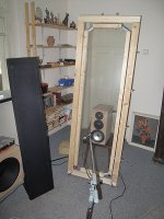
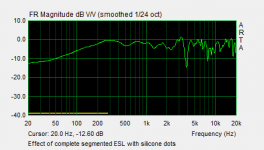
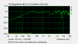
Recently I have decided to make several tests how an ESL element would impact propagating sound through it, by placing it between a dynamic system and a microphone. Measurement conditions:
Measurement type : MLS
Distance between mic. and dynamic system 25cm
All freq. response plots are calculated by using 3.5 ms window
10 averages
Neither microphone or dynamic system was moved or any settings changed during the measurements.
1) Freq. response of dynamic system only.
2) Freq. response after placing large stretched diaphragm in between, 6u thick, stretched to 1%
3) With bare ESL stator, assembled but without membrane
4) With complete wire ESL with silicone dots.
As it can be seen 3) and 4) shows a serious contribution to frequency response when impulse is coming from external excitations.
Regards,
Lukas.
Attachments
Last edited:
Hello Bazukaz,
Trying to measure impact of structure placed in between a point source and a microphone can be problematic because of diffraction around the edges of the structure. For example, you might further investigate test 2) for the diaphragm and try taking measurement sets with diaphragm in place and then removed with the frame in the same location. My guess is that a lot of the wiggles added to the 2nd plot is reflection/diffraction from the frame. With both data sets, you should be able to subtract off the contribution from the frame and get a better estimate for that of the diaphragm.
Smoothing the data by eye, it does look like the HF roll off due to the mass of the 6um film is visible starting above 10kHz.
Theoretical calculations would put the -3dB point at about 17kHz.
Hi,
At the moment I could not do the measurement of bare frame(no diaphragm) before it is glued on the next project. Maybe I will re-do the measurement some time after. It was just a rough evaluation experiment.
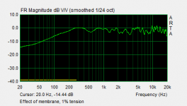
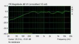
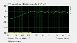
In fact I have done two measurements with membrane : low tension(similar to what can be obtained by heat shrinking) vs moderate 1% mechanical stretching. The purpose was to try observing any mid or high freq. resonance modes of the film. I could not draw any clear conclusions about this, effects should have been quite small.However in case of higher tension run the frequency response at top end looks a bit more ragged without smoothing. I am not confident about the results because the position of the frame was not carefully monitored, so it can be a contribution of reflections from it.
Your observation about HF roll off seem to be correct.
Below are two diagrams, with and without membrane, zoomed in and smoothed to 1/3.
At the moment I could not do the measurement of bare frame(no diaphragm) before it is glued on the next project
. Maybe I will re-do the measurement some time after. It was just a rough evaluation experiment.In fact I have done two measurements with membrane : low tension(similar to what can be obtained by heat shrinking) vs moderate 1% mechanical stretching. The purpose was to try observing any mid or high freq. resonance modes of the film. I could not draw any clear conclusions about this, effects should have been quite small.However in case of higher tension run the frequency response at top end looks a bit more ragged without smoothing. I am not confident about the results because the position of the frame was not carefully monitored, so it can be a contribution of reflections from it.
Your observation about HF roll off seem to be correct.
Below are two diagrams, with and without membrane, zoomed in and smoothed to 1/3.
Attachments
Bakukas,
I would think that a higher tension on the diaphragm would change the transfer of energy as the losses into the membrane would be lessened due to damping and the elastic properties of the membrane would also have to be considered. I know you wouldn't have any but a material such as Kapton would have a very high Young's modulus of elasticity. Thickness is also going to have an effect on transference of energy, the thinner the material is the more transparent it would be for the same material. It is an interesting experiment but what is your end goal? What exactly are you trying to accomplish with the experiment, is it only to look at the transparency of the material to sound passing through the membranes?
I would think that a higher tension on the diaphragm would change the transfer of energy as the losses into the membrane would be lessened due to damping and the elastic properties of the membrane would also have to be considered. I know you wouldn't have any but a material such as Kapton would have a very high Young's modulus of elasticity. Thickness is also going to have an effect on transference of energy, the thinner the material is the more transparent it would be for the same material. It is an interesting experiment but what is your end goal? What exactly are you trying to accomplish with the experiment, is it only to look at the transparency of the material to sound passing through the membranes?
- Status
- This old topic is closed. If you want to reopen this topic, contact a moderator using the "Report Post" button.
- Home
- Loudspeakers
- Planars & Exotics
- Electrostatic speakers as microphones?