Sorry, I understood from checking out your other projects that you are not a newcomer to electronics.
Clarification was mainly for others who might read this thread at a later date and don't have your background.
This is an excellent solution.
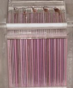
Attached pic shows high % open area mesh used as grounded safety shields on some models of King Sound ESLs.
Concerning HV bias contact corrsion:
Back when I was building stacks of test panels and Licron didn't exist, I come up with the following solution. I applied coating to the diaphragm leaving a 1/8" border inside the spacers. Copper tape was run around the panel in the middle of the spacers. Patches of Dag graphite were painted on to join the copper contact strip and coating.
This minimized leakage currents across spacers in humid conditions and avoided any possibility of corrosion. One of my favorite coatings at the time was Ivory dishwashing liquid soap thinned 1:3 with water and air-brushed on. Even that has shown no corrosion tendencies with the graphite after 15+ years.
Very slick! And the original soap coating has lasted 15+ years?
Very slick! And the original soap coating has lasted 15+ years?
Yup, I still have a few panels from the "early years" still playing with original soap coating.
I don't recall ever having problems with deterioration in the conductivity of soap coatings, but experienced many cases of contact corrosion leading to loss of bias charge.
At the time, soap provided a nice cheap way to get a high resistance uniform coating. It was much easier to deal with than rubbing graphite. However it has its own set of problems. It adds more mass than most other coatings, and remains slightly tacky so it tends to make vacuuming off dust more of a problem. It also changes resistance with humidity and, for whatever reason, is more prone to hissing/sizzling noises in high humidity/high bias setting situations.
My wife was fond of saying "...best sounding soap scum I've ever heard..."
Funny ....Thanks i needed That!
You know i have had a lose of the Panels bias feed right at the mylar... The F21 works great on the panel....but I pant dawn dish on the feed an mylar...work great.... never loses bias...an as you say it last.
you right about the added mass with soap if added to the open panel but it works...Diy you got lov it.
A friend just showed me a video of some spray-on-vinyl that can be used on cars. It can be peeled away again if you want it back to original. It costs $50 for 1 spray can, but in the forum, people are comparing it to Plasti Dip.
I visited the Plasti Dip website and found various paints and sprays that they produce. Just wondering if anyone has used this on stators. They have a paint that is just £14.50 for 750ml paint can and it says that 1 litre will cover 25sq feet at 15mils (0.3mm). Maybe this could be used to cover stators.
Quote from Plasti Dip website:
Any thoughtsPlasti Dip resists alkaline, acids, salts, moisture, abrasion, and most chemicals, and is an insulating dielectric coating.It will not crack, chip or peel, and will remain flexible even under severe conditions (-34ºc to +93ºc).Plasti Dip can be dipped, brush coated and sprayed. Add more layers for greater protection and grip.
Also... PLASTIC, RUBBER, FIBREGLASS and CONCRETE SURFACES!NOTE: Surfaces which are non-absorbent such as metals should be primed using our recommended Primers, which are available in Clear and Grey.
- WOOD: Seals and protects from weathering, and prevents splitting.
- METAL: Reduces vibration, deadens sound, and prevents corrosion.
- GLASS: Shatter proofs glass objects (available in clear).
I tried Plasti-dip.
The stuff in the spray can cost way to much for the amount of material you get.
I wasted about 3 cans of the stuff and never got a very good thickness with it.
Although I was trying to coat window screen, But it was $24 down the drain.
I did get the regular stuff and tested it and it looked like it may have some potential.
But it is very very thick and needs to be thinned.
I started to try it but I never got very far with it and it just dried up in the can when I found it again some years later.
I was thinking about using it on my TIG wire stators by tinning it and brushing it on.
If thinned it might work well as the problem for me was applying it to what I was working with.
This was way before I finally got a sprayer which was last summer.
I have a friend whom uses some polyurethane like the type you use on furniture.
I tried it on sample of wire mesh and it worked okay once it is thinned but it still beads up at the crosshair's just like spray paint does if you don't use a primer.
I am sure that it will work fine if you are using perforated metal though.
But it just takes longer to cure because it is petroleum based.
It doesn't play nice with spray enamel's either has I found out the hard way.
I have not yet done a dielectric strength test with poly yet, But I do plan to look more into it this summer.
I have found listings that it is only good for about 450 to 600v per mil and some that say close to 900v per mil.
It is the choice for Tesla coil builders and I have used it for years on my hand wound coils as well but I never did any stress tests on them yet.
As I said the Plasti-dip product looks promising with the limited testing I did do with it back in 2003, if you can learn to work with applying it.
By far I have found Spray clear acrylic enamel to be the cheapest high performance coating available.
There are some very nice industrial coating with some outlandish specs of 5Kv per mil and more.
I would expect them to preform well for the amount money some of them cost.
The problem is trying to get a source of them.
I tried one of the HV motor spray insulation's as well and it failed miserably.
This was before I was able to take a more scientific approach to HV testing of such coatings, But as it turned out I wasn't even barely getting to 5Kv when the panels started to arc.
This was the main reason I was hard pressed to build my variable HV supply as it is a very precision device and was when I found out what the actual voltage was that they were breaking down at.
The power supply ended up being much more than I had expected it to turn out to be.
I have plans to test some more coatings but I have kind of put it on a back burner since I figured out how to properly use the spray paint method with excellent results.
Another really good quality product is using automotive paints as they can be had in bulk and is cheaper in the long run, Providing you have the tools to apply them.
Typically there data sheets say they are good for about 800v to 1100v per mil but it wouldn't surprise me if they do better than this.
Beware though some are only rated for about 450v per mil by there data sheets, if it is even listed.
All of this stuff is covered in the " High Dieletric coatings, fact or fiction" thread.
jer
Hi,
Just adding to Geralds post:
One should take the HV specs with a grain of salt. Especially if test procedures remain uncertain. A quite common test for laquers is to coat a flat sheet of metal and test with either DC voltages or low frequency AC of 50 or 60Hz. This test procedure will give larger numbers than anyone could reach in praxis on a punched sheet metal stator. If the laquer is agitated well before painting wo degassing, chances are high that air bubbles/pinholes will develop.
Similar tests apply to wires. Apart from magnet wire most wires are highvoltage tested only for LF AC voltages. With increasing change rate of dV/dt, hence rising frequency, the flashover treshold sinks. You can find the effect also in datasheets of film caps, at least those of Wima film caps.
Regarding the issue of painting stator sheets with spray cans.
Just one advice: "Forget it!" You won't achieve the homogenity and surface smoothness and quality that You require. Spray coating is not a terribly efficient way of coating. Even spraying a flat sheet 20-30% of the paint, maybe more, is wasted and not deposited on the sheet. Painting a punched sheet with an openness of up to 50% wastes more paint than putting it to a good use -- way too costly with cans. If You want to pant wet, use a proper spray gun or roll the paint on.
Powder coating is much more efficient and offers a good base coat onto which one can add layers of wet painting for improving insulation and for optics.
jauu
Calvin
snip
You can vari the bias voltage by choosing different taps along the multiplier stack or you can use a chipamp to power the supply stepup tansformer as I had mentioned earlier.
This would be much easier to do then developing some some sort of switching type.
I took me a couple of months and many blown FET's to develop my circuit into a reliable one.
A chipamp makes this much easier to do. snip
When I built a HV ladder long ago, I soldered a wire with an alligator clip to the top voltage tap and then I could clip the alligator clip to any intermediate voltage point in order to lower the bias voltage output to the panels.
Ummm, after 30 years, about time to replace the old HV ladder esp. with something adjustable. Not sure I have the inspiration to try Fry's chipamp construction. Anybody make inexpensive alternatives to the nice EMCO adjustable HV modules?
Ben
For those convinced about presence of high AC voltage in real life ESL @ higher frequencies.
If one apply 3.5kV AC @ 5kHz to a device shown,very intense discharge will occur, total gap consists of 3 air gaps 0.3 mm each and 4 isolators 0.5 mm each made of alumina (corundum ceramic to be exact).
So all numbers about 1:100 x-formers driven by kilowatt amps should be taken with a grain of salt: no way air gap of 1.5-2 mm can stand anything near number above with any kind of insulation 0.5 mm thick (teflon included).
Attachments
Last edited:
Anybody make inexpensive alternatives to the nice EMCO adjustable HV modules?
One option is to use a Royer oscillation module from a CCFL driver, available from many online electronic supply distributors. They usually run at 20kHz - 50kHz and put out 600VAC to 900VAC depending on the CCFL tube they were designed to drive. The output voltage is proportional to the input voltage and they have plenty of current capability. Full output voltage usually achieved with 12VDC input. With the high frequency, required filter cap size is reduced.
Just search for “CCFL inverter” from your favorite supplier.
This is the one I have been using:
CXA-L10L TDK Corporation | 445-1622-ND | DigiKey
I use an LM317 to vary the voltage input to the module.
With 5 stage multiplier using 2kV rated diodes and caps I can vary the voltage from 500 to 6000 Vdc.
Higher voltages easily achieved with more sections thanks to the high oscillation frequency.
Last edited:
Thanks much. Not quite as simple as a single EMCO module, but easy to build. The EMCOs also have specs for their input voltage versus their HV output - not likely to be terribly accurate, but in the ballpark.
Dayton-Wright owners, who have a 17kV module in their "interface box," routinely move their bias voltage up and down with the change of humidity of the seasons. My tweeters (Dennesens) prolly would benefit from that kind of bias voltage tuning option.
I suppose it is hopeless to be able to calibrate, dial-in, and re-dial-in output voltages with a pot controlling the DC drive voltage? HV ladders and ESLs just aren't stable like that. Alternatively, I could make a hard-wired 1000:1 divider and measure output voltage with a DVM whenever I felt like it.
(Sorry for the detour, but HV has a whole lot to do with panel efficiency.)
Ben
Last edited:
I suppose it is hopeless to be able to calibrate, dial-in, and re-dial-in output voltages with a pot controlling the DC drive voltage? HV ladders and ESLs just aren't stable like that. Alternatively, I could make a hard-wired 1000:1 divider and measure output voltage with a DVM whenever I felt like it.
Sure, the output voltage can be marked on the dial that adjusts the DC voltage input to the module. The output increases linearly and repeatable, so it is easily set once the dial has been marked. I wouldn't be surprised at all if the EMCO modules were built using a similar circuit to the CCFL module followed by a built in multiplier section.
Those are neat little modules Bolsrest!!
Adapting a feedback regulation circuit like I used would be a breeze if it were to be so desired.
I get a very stable regulated output of 1kv out per .5v of control voltage input with my circuit.
It appears that, that module could drop right in replacing my whole HV generating stage before the multipliers.
Great Find!!!!
Cheers!!
jer
Hi,
btw. Pollin, a german company selling loads of cheap stuff and leftover always has some interesting CCFLs on offer, like this one CCFL_Inverter_TDK_TBD281NR_3 for just 2,95€
jauu
Calvin
btw. Pollin, a german company selling loads of cheap stuff and leftover always has some interesting CCFLs on offer, like this one CCFL_Inverter_TDK_TBD281NR_3 for just 2,95€
jauu
Calvin
Pollin, a german company selling loads of cheap stuff and leftover always has some interesting CCFLs on offer, like this one CCFL_Inverter_TDK_TBD281NR_3 for just 2,95€
Nice Price
Looking at the extra components on the board, this is most likely a dimmable inverter. Make sure you can get the datasheet so you know how to control it. Some dimmable inverters require a digital or PWM control input to operate. Others require just a simple analog control input.
With a little inspection, you should be able to bypass all the control circuitry and hook power straight to the Royer inverter section.
- Status
- This old topic is closed. If you want to reopen this topic, contact a moderator using the "Report Post" button.
- Home
- Loudspeakers
- Planars & Exotics
- ESL Panel Efficiency - First Build