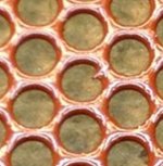
Syborg, in your second picture I noticed a sharp point in one of the holes.
It is areas like this that can and will wreck havoc on your newly built panel.
Especially when you start to crank it up.
You should consider removing this sharp point and then add some more coats to the coating.
Especially along the edges .
Even though you may have passed an arc test with your bias supply you will be applying well over 10KV to more than 20KV p-p across the stators on music peaks.
The high frequency ones are the ones most prone to cause punch thru of the stator coatings.
I was pushing 25KV P-P when my panel lit up like an arc welder on the side and finally on the edge on the inside from the very same bad spot that had been repaired before.
Burning the stator very badly.
Once it burns it leaves channels of carbon left behind buried in the coating and this is like little rivers that are just like exposed wires at a high voltage.
Very difficult to real seal once burned and usually requires completely stripping it down to the bare metal to reseal it as Charlie had mention.
Cheers !!
jer")
It is areas like this that can and will wreck havoc on your newly built panel.
Especially when you start to crank it up.
You should consider removing this sharp point and then add some more coats to the coating.
Especially along the edges .
Even though you may have passed an arc test with your bias supply you will be applying well over 10KV to more than 20KV p-p across the stators on music peaks.
The high frequency ones are the ones most prone to cause punch thru of the stator coatings.
I was pushing 25KV P-P when my panel lit up like an arc welder on the side and finally on the edge on the inside from the very same bad spot that had been repaired before.
Burning the stator very badly.
Once it burns it leaves channels of carbon left behind buried in the coating and this is like little rivers that are just like exposed wires at a high voltage.
Very difficult to real seal once burned and usually requires completely stripping it down to the bare metal to reseal it as Charlie had mention.
Cheers !!
jer
Attachments
Last edited:
Hi. Very interesting thread and I'm keen to experiment with ESLs, and as I am an electrical engineer by trade, I know of the dangers of high voltages and proper insulation. I have a few questions if anyone can answer.
1) If I were to build an ESL of about 4ft square surface area, could my LM4780 Gainclone amp drive it, It has +/- 25 volt rails?
2) At work we use perforated stainless sheet which has 6mm holes in it. It is roughly 1.5mm thick. It is actually used for sewage screening, but looks like it could be used for the stators, any thoughts?
3) What is the best way of insulating the stators? I heard that powder coating isn't usually that successful as the holes in the sheet can get pretty small. I have used Plasti-kote before for various DIY stuff, would this be any good for stator covering?
Plasti-kote, Welcome to the home of spray paint
4) For the DC bias, I have seen mains supply versions using a 6v to 230v transformer and then a trippler circuit and I have also seen 15V DC supply circuits which use a 555 timer to create a SMPS to get the voltage. Which is the best method? The mains supply one seems simpler and I'm not a fan of SMPS in audio.
5) My current set-up is a DIY LM4780 amp, DIY DAC and DIY full range speakers (CSS EL70) in the Lake District Series, Derwent cabinets (Designs from frugal-phile website) along with some DIY super tweeters. I am very happy with the sound produced from these, so is it worth the effort to build some ESLs?
6) If I build some ESLs, I will probably use a 8 inch or 10 inch woofer for the low-end. Would a crossover point of about 250Hz be OK and would a 2nd order crossover be OK?
7) Could passive crossovers be used before the step-up transformer? As I don't really want to build active crossovers, as I am happy with my amp and don't really want to bi-amp the hybrid ESLs/woofer.
Thanks in advance for any help
I have had good results from using spray paint and those tests can be found here,
http://www.diyaudio.com/forums/plan...tric-coatings-fact-fiction-2.html#post2893839
and here,
A Segmented Stator Desktop ESL
A Segmented Stator Desktop ESL
Do use a primer and stay away from any pigmented paints as a top coat.
A base coat is fine for color then just use clear after that.
I have gotten between 1700v to 2100v per mil before breakdown occurs using typical off of the shelf types.
I think Stainless would be a nice material to work with as long as the paint will stick to it well and as long as it is flat with no wraps or ripples.
I think the biggest issue you will have is getting rid of all of the sharp edge as it is some pretty hard stuff.
6mm holes are large and I wouldn't use anything larger.
Many have had good results using that size holes, But personally I have not tried it yet.
The Bias supply can be made from any method you chose fit and are willing to go through to get it working should you choose to do a switching type of some sorts.
All that is required that you have a high voltage at a low current, Typically from about 2.5Kv to 6.5Kv.
Here are a couple of links for Bias supply's.
One is the one I designed and is variable although it is a bit of an undertaking to build.
And the other one found on Jazzman's ESL (Charlie) site.
Does anyone have schematics of a varible HV power supply
Jazzman's DIY Electrostatic Loudspeaker Page: The Electronics Package
Another method that works well to make a variable supply is to use a small chipamp fed from a opamp sine wave oscillator with a volume control feeding a low voltage power transformer in reverse into the voltage multiplier stage.
Anything above that 7kv and you start to run in to dielectric breakdown issues especially if you are using a smaller D/S of about .0625".
Your chipamp may power it okay but don't expect a lot out of it.
The impedance of these speaker systems drop to and/well below 2ohms at the higher frequency's depending on the transformer step up ratio and the transformers themselves.
If you follow the guidelines shown in some of these threads you will have a decent working system.
I would consider using I paralleled chipamp setup.
I have been planning on building a Pair of PA200 or PA250's out of the 5 Lm4780's I do have.
I was thinking of two PA200's and use the 5th one to power a pair of my 8" subs for my next bigger model.
But I do have some very big amps at my disposal so it is last on my list of things to do.
You might want to consider going with a 12" woofer for the lower end as even a 10" can run out of steam quickly depending on your listening style.
It all depends on what you have already available.
I have a bunch of 8's laying around and in some sim's that I have done just 2 or 3 of per side can put out some very decent SPL's.
I used just one of them when I first powered up my little panel for the first time in years.
It was loud enough to make it difficult to hold a conversation and it was being powered off of a cheap CD player type all one one box.
There is a picture of that setup in one of these threads.
A 1' X 4' panel can really get up there in SPL's if it is driven properly.
A passive crossover can be designed, But it will take a lot of testing to get it right and it is much cheaper to just get an active crossover or build one out of a few opamps.
Not to mention the cost of the components to build a quality passive design.
Do consider going the active route!!
If you want to get down to 250Hz then you will need to go with a large D/S of say at least .075" to .110" or so.
Using a large D/S means higher voltages and step-up ratio's to make up the difference in loss of efficiency.
Also the transformer is an issue here as well as the core saturation points of your typical power transformer will be about 350hz to 330hz for a 40Vrms signal into the 6v winding.
A 100 watt core may fair a little better in this range but even the one I have been testing can only get to 300hz max for a 40Vrms input.
If you don't go above 20Vrms to 30Vrms it may be possible to get good results down to 250Hz.
The cost of getting to a lower crossover frequency is efficiency, due to core saturation.
The step-up ratio sets the maximum SPL at this frequency and if you use a higher step-up ratio then you lower your impedance that your amplifier sees.
So therefore you have to add more cores.
Unless you wind your own transformer.
Some have used as many as 8 per speaker to get a lower frequency response.
I think 4 would do it and is what I use for my little panels.
I will be going over this soon in another thread as I am going over some measuring technique issues this very moment.
So, there are a few trade off's to consider and it just takes a little planning is all.
Most the that trial and error stuff has already been done in these threads.
Cheers !!!
jer
Last edited:
Hi,
It depends on final capacitance of the panel, but should be ok in most cases.
Sheet with 6mm holes is not the best candidate if you are targeting uniform electrical field and good efficiency. 3-4mm should be much better.
Powder coating of just a single layer of polyester is almost equal to nothing in terms of insulation. However some people have had had success with multiple layers of powder coat made from different materials. Problem is that most of powder coaters won't accept to do this.
I do not know Plasti-kote but I can say that you should prepare for a difficult job if you want to make perforated sheets insulated well(>>8 kV or so) over it's entire area. You will need to round sharp edges of holes and spray many, many layers of paint. If you want to use canned stuff then prepare to buy loads of them. The problem with perf. stators are edges of each hole.
First thing you should determine if you need a variable supply. If not the easiest and perhaps most reliable way is to connect several small transformers back-to back and then use a voltage multiplier. For example, one transformer is connected to mains 230:12V. 12V winding is loaded by 2 or 3 small transformers connected in reverse, so you end up with 400-600 volts AC(roughly). Then a several stage ladder of volt. multiplier depending on what voltage do you need.
It can be used but IMO it's far from optimal, especially in case of ESLs. disadvantages:
a) Difficult to tune in and do any equalization
b) Increased distortion of step-up transformer because source impedance is increased at lower frequencies
c) Eats up efficiency and so on
I have to disagree. For frequencies of 250Hz and up you don't need any higher D/S than about 1mm or 0.04" as long as the construction is accurately and properly implemented, and the fundamental resonance mode is filtered out. Making lower D/S spacing is preferable as you need much lower step up ratio transformer.Capacitance is multiplied by turns ratio squared so you can quickly end up with full power bandwidth of just a few kHz.
My personal view is that wire stators are by far superior to perf. metal for DIY, unless you are targeting curved designs like MLs. I suggest you read the following thread for introduction(which is quite old):
http://www.diyaudio.com/forums/planars-exotics/71171-wire-stator-gluing-method.html
Regards,
Lukas.
1) If I were to build an ESL of about 4ft square surface area, could my LM4780 Gainclone amp drive it, It has +/- 25 volt rails?
It depends on final capacitance of the panel, but should be ok in most cases.
2) At work we use perforated stainless sheet which has 6mm holes in it. It is roughly 1.5mm thick. It is actually used for sewage screening, but looks like it could be used for the stators, any thoughts?
Sheet with 6mm holes is not the best candidate if you are targeting uniform electrical field and good efficiency. 3-4mm should be much better.
3) What is the best way of insulating the stators? I heard that powder coating isn't usually that successful as the holes in the sheet can get pretty small. I have used Plasti-kote before for various DIY stuff, would this be any good for stator covering?
Powder coating of just a single layer of polyester is almost equal to nothing in terms of insulation. However some people have had had success with multiple layers of powder coat made from different materials. Problem is that most of powder coaters won't accept to do this.
I do not know Plasti-kote but I can say that you should prepare for a difficult job if you want to make perforated sheets insulated well(>>8 kV or so) over it's entire area. You will need to round sharp edges of holes and spray many, many layers of paint. If you want to use canned stuff then prepare to buy loads of them. The problem with perf. stators are edges of each hole.
4) For the DC bias, I have seen mains supply versions using a 6v to 230v transformer and then a trippler circuit and I have also seen 15V DC supply circuits which use a 555 timer to create a SMPS to get the voltage. Which is the best method? The mains supply one seems simpler and I'm not a fan of SMPS in audio.
First thing you should determine if you need a variable supply. If not the easiest and perhaps most reliable way is to connect several small transformers back-to back and then use a voltage multiplier. For example, one transformer is connected to mains 230:12V. 12V winding is loaded by 2 or 3 small transformers connected in reverse, so you end up with 400-600 volts AC(roughly). Then a several stage ladder of volt. multiplier depending on what voltage do you need.
7) Could passive crossovers be used before the step-up transformer? As I don't really want to build active crossovers, as I am happy with my amp and don't really want to bi-amp the hybrid ESLs/woofer.
It can be used but IMO it's far from optimal, especially in case of ESLs. disadvantages:
a) Difficult to tune in and do any equalization
b) Increased distortion of step-up transformer because source impedance is increased at lower frequencies
c) Eats up efficiency and so on
If you want to get down to 250Hz then you will need to go with a large D/S of say at least .075" to .110" or so.
Using a large D/S means higher voltages and step-up ratio's to make up the difference in loss of efficiency.
I have to disagree. For frequencies of 250Hz and up you don't need any higher D/S than about 1mm or 0.04" as long as the construction is accurately and properly implemented, and the fundamental resonance mode is filtered out. Making lower D/S spacing is preferable as you need much lower step up ratio transformer.Capacitance is multiplied by turns ratio squared so you can quickly end up with full power bandwidth of just a few kHz.
My personal view is that wire stators are by far superior to perf. metal for DIY, unless you are targeting curved designs like MLs. I suggest you read the following thread for introduction(which is quite old):
http://www.diyaudio.com/forums/planars-exotics/71171-wire-stator-gluing-method.html
Regards,
Lukas.
Yes, I will have to agree with your disagreement!! He,he,he
I should have stated 250hz and below!
But typically the next size in thicknesses for materials that are found in the .050" to .0625" range is .080" to .093".
Depending on your method of construction it can be made adjustable using what is available in your area.
Powder coating has a few issues.
I have used it but you will spend more time getting your powdercoater to do them correctly than you will with just painting them.
Powder coating is more brittle than paint and it can develop micro cracks in the coating and this will lead to failure of the panel.
I had to use two coats to make it work on some wire mesh and the coater refused to do a third coat for whatever reason, I never got one either.
It could have been the type of material that was used.
Seven years later I had to re-coat them again with some clear acrylic due to the cracks causing weak spots and they eventually failed and I burned them up.
But a lot of this was my fault from seeing how high I could push the voltages too.
It can be done yourself but it will take some time to get it right, with lots of experimenting for sure.
I must say I do prefer the wire method as well and it can be a lot cheaper on materials if you are resourceful.
Have you thought about segmenting the panels into several smaller ones?
This is where the wire method is very nice because you can electrically segment the stator's
This will help to widen the horizontal dispersion of a wider panel of 12" should you not physically segment them in smaller sections.
And not to mention it will make for an easier load on the amplifier if it is electrically segmented as well.
This is were a larger D/S will play for a major importance as I did not have good luck with diaphragm stability on my 8" wide panels with a D/S of .0625 especially below 300Hz to 200Hz.
I ended up with 2mm to 2.5mm and just increased the bias voltage to make up loss in efficiency.
Diaphragm tension had a lot to do with this as well since I didn't have a mechanical stretcher and I am using .25 mil (6um) mylar.
Just I few more thoughts.
jer
Last edited:
This is were a larger D/S will play for a major importance as I did not have good luck with diaphragm stability on my 8" wide panels with a D/S of .0625 especially below 300Hz to 200Hz.
I ended up with 2mm to 2.5mm and just increased the bias voltage to make up loss in efficiency.
Diaphragm tension had a lot to do with this as well since I didn't have a mechanical stretcher and I am using .25 mil (6um) mylar.
Hi,
ESL manufacturers I know of used bias voltages in the order of about 2kV/1mm. There are good reasons not to exceed this by much :
a) Air starts to ionize
b) Diaphragm sticking to stators
It's not easy to compensate significant increase of d/s spacing by only putting a lot more bias voltage because of limitations above. Remember doubling d/s spacing requires four times the voltage to get efficiency back.
To get 6um mylar stable on 8" panel with 2mm spacing requires either strong mechanical tensioning or adding more supports. One ESL manufacturer who is now out of here(Capaciti) has mentioned multiple times against using strong tension due to partial resonances of membrane.
I have found a quite interesting applet for simulating modes of a rectangular membrane :
Rectangular Membrane Applet
It is difficult to tell how many of these will actually show up in measured performance.
In terms of D/S spacing I think 2.5-3 mm is already enough for full range operation. I have been testing panels with only 2mm full range and it didn't strike stators with music. Test signals could do this if targeted at resonance with high levels.
Regards,
Lukas.
Last edited:
Yes, I agree.
I have found that about 2mm is good for getting down to that range on both my 3.25" and 8" wide panels.
If one where to use the sticky tape method of construction then there are only A few choices of material to choose from and the .0625" thick stuff would be marginal for use at the lower frequency's.
I will be exploring this in greater detail soon as my new panels D/S is adjustable as was my last one and is set at around 1.85mm.
As little as a 15% to 30% increase of the D/S spacing can make your break your low frequency performance at such low frequency's due to not having enough room for excursion.
And the increase of bias voltage would still not be more than about 50% or so to make up the difference.
I have measured close to about a 6db increase of efficiency for every doubling of the bias voltage.
That is 12db more going from 3kv to 12kv but as I stated before, anything much above 7kv is impractical due insulation issues.
It was not at all easy to get to those high of voltages with out issues.
I did get DS clipping with my smaller 3.25" wide panel and had to increase the DS spacing to reach high SPL's at below 200HZ or so to .090" from about .072" total spacing.
And yes I took a hit in the efficiency and it was very noticeable.
Being that they have a naturally rising frequency response Diaphragm excursion is not an issue at higher frequency's.
I do have to admit that the voltages I have reported that I am using are true but are a bit on the extreme side of things.
A larger panel won't need such high voltages to perform well but when you want to get down below about 300Hz the transformer and the D/S start to become some things to consider in the design.
jer
Thanks for the info and the link to the other thread (post 24). The wire method looks interesting as I can get hold of some enamel coated motor winding wire, which could work well. In the other thread they are using light louvres or egg crates to help hold the wire, so do the final panels have the louvres still attached, but obviously facing away from the centre where the mylar sheet is to allow for a close gap?
If you use a magnet wire be sure that you get the heaviest insulation build you can.
Even at that I am not sure how much it can withstand.
PVC coated wire is what is commonly used and is good for about 500v per mil.
I have always wanted to try some Kynar coated 30ga wire wrap wire and a few have claimed they used it with good results as well.
The plastic grid method is how the Acoustat's are made and is what inspired me to build my first panels only I used spray enamel on aluminium window screen for my stators and this worked very good.
I sealed the sharp cut edge with some clear silicone.
You must first be sure that the coating thickness is plenty becuase any later add coats do not bond to the silicone to create a good seal.
It was a just one sharp wire on the edge that wasn't buried deep enough in the silicone that started to leak and eventually gave me problem when I ventured past 7Kv of bias voltage and more than 20Kv p-p across the stators.
Here is another very good thread that deserve a good read on wire stators,
http://www.diyaudio.com/forums/plan...nstruct-cube-louver-acoustat.html#post2141539
It is by far the cheapest method of construction and still yields a great sounding product!
Enjoy!!
jer
Last edited:
Hi,
I have not tried enamel coated wire but there seems to be some people who got it right and some who did not. It looks like the wire is rather picky to how much you stretch it depending on type and tends to develop micro cracks if abused too much. As far as I know some amount of insulation defects are allowed per length; it could be in the order of a couple defects per 100m or so. It is acceptable in a motor or transformer where coincidence of having two defects at the same spot is extremely small. This is not the case in ESLs.
Common single stranded PVC wire like H05 is more forgiving IMO. Despite it's typical voltage rating of about 500V it can withstand by far more and is usually tested at 2 or 2.5kV in the factory. This is more or less similar to what acoustat has used.
BTW there is no absolute necessity to use louvres to support wires; one can construct frame from other materials and frequently it has some advantages, like being easier to glue wires to and/or more structural rigidity.
Regards,
Lukas.
Thanks for the info and the link to the other thread (post 24). The wire method looks interesting as I can get hold of some enamel coated motor winding wire, which could work well. In the other thread they are using light louvres or egg crates to help hold the wire, so do the final panels have the louvres still attached, but obviously facing away from the centre where the mylar sheet is to allow for a close gap?
Thanks for the info. So it seems that it is best and easiest to use PVC coated wire to stop any leakage. Would the wire inside 'twin and earth' like the link below work well?
1TE5 1MM TWIN & EARTH CABLE 50MT 6242Y£20.63 1TE5 1MM TWIN & EARTH CABLE 50MT 6242YPrices are exclusive of VAT which will be added when you check out Fairalls Builders MerchantsFairalls Builders Merchants
The cross sectional area of each core in this cable is 1mm, so the diameter of the core is about 1.2mm and the blue and brown insulation is probably about 0.5mm. Would this be a good candidate? and if so, would a gap between the wires of 1.5mm be OK?
No this is not good. You should be seeking for single non flexible wire with monolithic conductor.Use black if available.Something similar to H05V-U or H07V, like :
H05V-U / H07V-U - harmonized PVC solid bare copper
Then you will have to pull the wires real hard and flatten them. A kind of tool is required. You must get into plastic deformation of copper. One relatively simple way to build the jig is to use threaded rods welded together. If you don't have access to welding equipment then perhaps you could find a garage to do this for you(as did I ). This way you can get two stators wrapped at once.
In case you are going to use light louvres welding is not needed as a single threaded rod can be chosen to be thicker than two stators.
See pic attached.
H05V-U / H07V-U - harmonized PVC solid bare copper
Then you will have to pull the wires real hard and flatten them. A kind of tool is required. You must get into plastic deformation of copper. One relatively simple way to build the jig is to use threaded rods welded together. If you don't have access to welding equipment then perhaps you could find a garage to do this for you(as did I
). This way you can get two stators wrapped at once.In case you are going to use light louvres welding is not needed as a single threaded rod can be chosen to be thicker than two stators.
See pic attached.
Attachments

Last edited:
Hi Bazukaz. The link I posted is solid core cable and is fairly stiff compared to flex cable, what is the difference between that and the link you posted? Also, what size is the wire used in the picture and what thread is the bar?
By the way, very simple and nice jig.
The wire you posted is double insulated with three wires inside. How do you plan to extract these wires for hundreds of meters?
I have used 0.5mm^2 wire with 0.6mm insulation. The threaded rods are 27mm in diameter each.
BTW I want to warn that if you plan to use plastic louvers it may not be easy to glue relatively thick wires to it reliably as gluing surface of plastic is very thin, and material is somewhat brittle. Acoustat used to dissolve the same louvre material in methylene chloride and use it as a glue with a viscosity like a thick syrup. I have tested this under DIY conditions and it seemed to work.
Later I have decided to make frames from other materials which accept many different glues and are stiffer.
Regards,
Lukas.
Thanks again. I realise the link I posted has 3 cores inside of it, but by pulling the centre core (earth) back on itself it simply rips open the grey sheathing and you can take easily take out the other wires. Maybe 1mm^2 cable is too large anyway.
I like the idea of your jig, using a continuous wire wrapped round and around and making 2 stators at the same time. How much stretch did you put on the wire after you wound it? and how did you fix the ends after you separated it into 2 stators. Sorry for all of the questions, I want a good idea of what needs to be done before I start playing around.
I like the idea of your jig, using a continuous wire wrapped round and around and making 2 stators at the same time. How much stretch did you put on the wire after you wound it? and how did you fix the ends after you separated it into 2 stators. Sorry for all of the questions, I want a good idea of what needs to be done before I start playing around.
Thanks again. I realise the link I posted has 3 cores inside of it, but by pulling the centre core (earth) back on itself it simply rips open the grey sheathing and you can take easily take out the other wires. Maybe 1mm^2 cable is too large anyway.
If you can find single wire it would be a lot simpler to do so and there is no risk of accidentally damaging the insulation while pulling center conductor out of the 2nd layer.
I am not sure if H05 wire(I think its an EU standard) is available in UK but in LT it costs like 8 EUR/100m.
I like the idea of your jig, using a continuous wire wrapped round and around and making 2 stators at the same time. How much stretch did you put on the wire after you wound it? and how did you fix the ends after you separated it into 2 stators. Sorry for all of the questions, I want a good idea of what needs to be done before I start playing around.
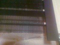
I do stretch stretch the wire to about 1-2% and then release to a point when they lose tension again. At this stage it is easy to see if there are still some small radius wrinkles in wires. If yes, stretch a bit more. If no, then stretch just enough to get them straight and then proceed to gluing to stators.
It is not a good idea to glue wires under high tension; combined force of them can be very high and will deform or even break supporting construction when removed from the jig.
After that there are 3 steps left:
1) Clean ends of each wire. It is a bit of a pain.
2) attach spacers at the ends(glue or otherwise)
3) Solder wires either together or with segmentation resistors
Sorry for poor quality photos but I do not have a better camera at this time.
Photo below is of not completed stator yet, after being removed from the jig.
Regards,
Lukas.
Attachments
Last edited:
Very neat. I was wondering whether this idea would work.....Building the stator using 1inch x 1/2 inch oak.
Putting two 4 foot lengths about 1 foot apart and then using pieces of the same oak glued (or joined using half cut joints) every 8 inches up the length to create a ladder. The wire would then be put onto the stators using a jig similar to the one you showed a couple of posts ago. Now instead of using glue to hold the wire in place, I was thinking that the 3m double sided foam tape could be laid over the top of the wires when the 'steps' of the ladder are. This would then act as the spacer when attaching the Mylar.
Would this work, or would putting foam tape every 8 inch create a kind of array of smaller panels with a higher lowest frequency response?
- Status
- This old topic is closed. If you want to reopen this topic, contact a moderator using the "Report Post" button.
- Home
- Loudspeakers
- Planars & Exotics
- ESL Panel Efficiency - First Build