Very neat. I was wondering whether this idea would work.....Building the stator using 1inch x 1/2 inch oak.
Putting two 4 foot lengths about 1 foot apart and then using pieces of the same oak glued (or joined using half cut joints) every 8 inches up the length to create a ladder. The wire would then be put onto the stators using a jig similar to the one you showed a couple of posts ago. Now instead of using glue to hold the wire in place, I was thinking that the 3m double sided foam tape could be laid over the top of the wires when the 'steps' of the ladder are. This would then act as the spacer when attaching the Mylar.
Would this work, or would putting foam tape every 8 inch create a kind of array of smaller panels with a higher lowest frequency response?
I am not sure about oak(which is far better than common woods for sure) but I think plywood is better than plain wood to do something like this. It does not tend to bend over time and thermal/water expansion is a lot more consistent across its width and height.
b) I do not know what specific 3M tape you are talking about. I have had very bad experience with tapes, although some people have used some 3M which I think must be rigid and not foam. Most of double sided tapes creep over time(that can be easily within several hours) and release tension of mylar as their glue never dries out. Result is wrinkles on corners which do buzz and lost tension.
I would greatly suggest to first build some experiments before planning for final build. It's not an easy road as it might seem, with stones and ditches
")
Last edited:
Here Is a very nice article of a wire stator design that really inspired me to final build my first ESL's, although I used a different method I stiL refer to this one quite often,
Do It Yourself - Electrostatic Speakers - Project: ESL-220-30 by Marc Schroeyers
There are many more good articles that may give you some ideas as well here,
Do It Yourself - Electrostatic Speakers
Some are wire designs and some use other methods,
Oak will look very nicely for the frame but it can warp over time as it dries out more.
You might want to give them a heavy coat of polyurethane especially on the side of the frame that wire will be secured to as wood will conduct at high voltages.
Sheathing the wood rails with some acrylic plastic sheet is another idea that may work well.
I don't think think double sided tape will secure the wires properly (especially for long term).
You are better off using a good strong glue such as epoxy.
jer
Last edited:
Thanks for the links Geraldfryjr, look very handy, will have a good look through when I have some time. Bazukaz, you say that the double sided 3M may creep over time, I got the idea of 3M tape for Jazzman's build:
Jazzman's DIY Electrostatic Loudspeaker Page: Building the Stat Panels
Is there a better way to space the stators from the membrane? What method do you use?
I asked in post #40 about putting foam as spacers on every wire support:
'would putting foam tape every 8 inch create a kind of array of smaller panels with a higher lowest frequency response'
After a little more reading, Am I right in saying that one large area of rotar, would be better than lots of smaller areas to help with lower frequencies?
Typically ESL's have a flat response regardless of their shape or size in the nearfield.
They do present a rising response of about 6db per octave as get farther away from them as per the rules of dipole action.
Segmenting the panel into sections does two things,
1# It can raise the fundamental resonance of the diaphragm depending on the diaphragm tension.
This will have an effect on the lower frequency response curve.
Typically you want to stay at least one octave above this frequency.
If you are building a Fullrange panel then this maybe beneficial in the design if the frequency is low enough.
2# Segmenting the panel into smaller section helps to widen the angle of dispersion of the higher frequency's emitted from the panel.
I explain this in greater detail in the thread of my latest build here,
A Segmented Stator Desktop ESL
The smaller the dimension of the panel the wider the dispersion of the highest frequency's it will be.
This is the same reason that tweeters are no bigger than 1" wide and midranges are typically 3" to 5" or so and so on with woofers as well.
Foam tape works great IF there is plenty of surface area to bond to as in the perforated metal stator design.
Even then I have read reports of bonding issues if the metal is not perfectly flat but it does work great if done properly.
The main draw back to this method is that once they are bonded they are for life and should anything cuase you to need to take them apart, such as leakages or arc breakdown in the stator coating, it is a PIA to get them apart to fix it and then you have to throw away the diaphgram and apply a new one as most likely it will be destroyed coating and all.
Wire does not have enough surface area in order for it to solidly bond to foam tape.
I can get down to 200Hz just fine with my little panel of 3.25" width as long as I have enough room for the diaphram to move (Xmax or D/S).
If you notice Charlie's panels are actually 3 sections that are about 3.5" wide and our friend Mavric chose to build his a little wider with a 16" wide panel and 3 sections using the same method as shown here,
http://www.diyaudio.com/forums/planars-exotics/162127-different-ideas-esl-panels-4.html#post2142850
I can assure you those things rocked and were very loud!!!
jer
Hi,
Some double sided tapes that are designed for high shear performance can work but they are not cheap.
A quote from
FAQs
The condition is that you use only Scotch Brand 3M tapes which employ high performance adhesive types 467 or 468. Other tapes lose their grip over time.
It is possible to understand why people use double sided tapes for ESLs constructed from perforated steel : it is simple to build.
However I you plan to build a wire ESL than there is no a single advantage of this IMO.
A relatively simple build is to use one light louvre. Standard size is something like 125x60 cm if memory serves me well. Cut this to four pieces and it is enough material for two small panels sized about 125x15cm each down to about 300-400Hz. O thin PVC insulated wire with 1-1.2mm outer diameter would suit well with a D/S spacing of 1-1.5 mm.
No supporting strips are necessary for flat designs if you follow the rule that unsupported film width should be 70-100 times the d/s spacing.
Regards,
Lukas.
Thanks for the links Geraldfryjr, look very handy, will have a good look through when I have some time. Bazukaz, you say that the double sided 3M may creep over time, I got the idea of 3M tape for Jazzman's build:
Jazzman's DIY Electrostatic Loudspeaker Page: Building the Stat Panels
Is there a better way to space the stators from the membrane? What method do you use?
I asked in post #40 about putting foam as spacers on every wire support:
'would putting foam tape every 8 inch create a kind of array of smaller panels with a higher lowest frequency response'
After a little more reading, Am I right in saying that one large area of rotar, would be better than lots of smaller areas to help with lower frequencies?
Some double sided tapes that are designed for high shear performance can work but they are not cheap.
A quote from
FAQs
The condition is that you use only Scotch Brand 3M tapes which employ high performance adhesive types 467 or 468. Other tapes lose their grip over time.
It is possible to understand why people use double sided tapes for ESLs constructed from perforated steel : it is simple to build.
However I you plan to build a wire ESL than there is no a single advantage of this IMO.
A relatively simple build is to use one light louvre. Standard size is something like 125x60 cm if memory serves me well. Cut this to four pieces and it is enough material for two small panels sized about 125x15cm each down to about 300-400Hz. O thin PVC insulated wire with 1-1.2mm outer diameter would suit well with a D/S spacing of 1-1.5 mm.
No supporting strips are necessary for flat designs if you follow the rule that unsupported film width should be 70-100 times the d/s spacing.
Regards,
Lukas.
Thanks again for the info. I'm probably not going to start the panels until later this year, so I'm just gathering info at the moment.
I'm still not sure whether to use wire or perforated sheet, I like the look of the perforated sheet method, but obviously is harder to stop creeping.
I looked at the link to Charlie's panels (very nice) and want to know what people normally do to the front of the stator after they have used the double sided tape, as the tape obviously is visible through the holes and would be sticky and dirt would get stuck to it.
Just been looking at 3M tape!!! Very expensive. A 1 meter roll of foam double sided tape can cost £5! What thickness tape do people normally use? I suppose the thinner the better so you get a smaller d/s and larger SPL. What spacing do most DIYer's use.
Would this be any good for making the stators from:
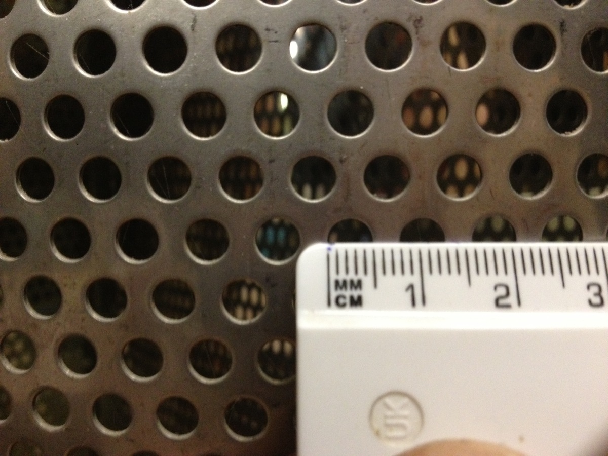
I think that maybe there is too much metal compared to some of the stators I have seen?
Would this be any good for making the stators from:
I think that maybe there is too much metal compared to some of the stators I have seen?
Last edited:
Just been looking at 3M tape!!! Very expensive. A 1 meter roll of foam double sided tape can cost £5! What thickness tape do people normally use? I suppose the thinner the better so you get a smaller d/s and larger SPL. What spacing do most DIYer's use.
Would this be any good for making the stators from:
I think that maybe there is too much metal compared to some of the stators I have seen?
.062" (1.5mm) thick tape works well for hybrid panels. I use this .062" thick x.75" wide x 35 yd roll, purchased from McMaster Carr ( McMaster Carr part number 7626A114):
McMaster-Carr
The tape will attract dust but that's not a performance issue. My speakers have removable grills which I typically leave on, and this keeps the tape clean. 3M says the white tape will yellow after a few years from exposure to UV, but they claim it will last for 25 years when used inside a typical home.
I agree that the perf metal shown in your photo has too little open area.
I would use either 40% or 51% open, with .125" diameter holes. I'm currently using 40% open perf, which I think is the lowest open area you should use.
Quad ESL 57 used considerably less than 40% open area, something like 20% or so.
The target is between 20-30% after insulating layer IMO. Lower open area can help in damping resonances and gives more field strength.
However I think holes are a bit too large in photos. It would suit an experiment perhaps.
Lukas.
The target is between 20-30% after insulating layer IMO. Lower open area can help in damping resonances and gives more field strength.
However I think holes are a bit too large in photos. It would suit an experiment perhaps.
Lukas.
Last edited:
Hi,
The 3M tapes work very well with metal stators, if the right type i.e the right combination of glue layer and the insulating material is found. Though it sticks to the stator like mud to the proverbial boot, warps in the metal sheets may lead to a loss of the joints.
There is a great number of 3M tapes to choose from and it is quite tricky to understand their numbering system. Tapes from the same material that differ in thickness may have totally different numbers. Thickness measurement in imperial or metric system gives totally different part numbers. 3M are way off of a simple logic regarding the part numbering.
The metal sheet in the picture looks like a RV5/8, which means "Rund, versetzt", round, staggered hole pattern of 5mm holes distanced at 8mm. This is kind of standard off of the shelf pattern. MartinLogan used a RV5/6 (or something very close in imperial measures).
I'd not use so big holes and so low opening, but on very large panels with high d/s value.
RV3/4 seems to be a very good compromise for metal sheets.
jauu
Calvin
This open area calculator might help.
Calculation of open area - RMIG
Here is one for wire mesh my material of choice,
http://www.wirecloth.com/cwc/percent.htm
jer
Calculation of open area - RMIG
Here is one for wire mesh my material of choice,
http://www.wirecloth.com/cwc/percent.htm
jer
Last edited:
Here is a picture of the material I made my very first panels out of.
It has 2.5mm holes on 5mm centers and has a open area of about 22.7%.
By the time I got a good coating on them of about 10 mil or so my open area had dropped to 12%.
They worked but the sound was restricted quite a bit and didn't get very loud at all.
It was just too restrictive.
Then I made a identically sized panel using wire mesh and my open area was about 4X that of my first panel.
What a big difference it made as far as the quality and especially the sensitivity.
The third panel I made used an even better coating material (powder coating) and this allowed for on even greater open area and higher voltages as well.
What a difference this made!!!
Your material has bigger holes and this will help a great deal compared to what I used.
That was when I got the idea of trying wire mesh as this gave me higher concentration of holes per area while still giving me a large open area.
The thin wires allowed enough room for a decent thickness of insulative coating as well.
This also allowed for a more uniform highly concentrated static field across the panel than what larger holes would allow.
Not to mention the cost difference between the two materials as I couldn't afford metal panels at the time.
jer
Attachments
Last edited:
I've been doing a bit more research and looking at various ESL builds and I really want to make curved mesh speakers. I prefer the look of them over the wire ones and making them curved will give a wider listening angle. At work we have a sheet metal roller and I can get the mesh powder coated locally. Just need to find some mesh with a larger open area. What would you think the open area of the mesh I showed in an earlier post would be after powder coating?
Also, I think the metal sheet roller at work can only accept sheets up to 2 1/2 feet wide. Would a panel 2 1/2 feet high and 1 foot wide be OK for 400Hz and up, or would it be better to have two panels per channel?
Here is an interesting blog I found on making curved ESLs:
https://sites.google.com/site/eslarray/home/project-history
Last edited:
I've been doing a bit more research and looking at various ESL builds and I really want to make curved mesh speakers. I prefer the look of them over the wire ones and making them curved will give a wider listening angle. At work we have a sheet metal roller and I can get the mesh powder coated locally. Just need to find some mesh with a larger open area. What would you think the open area of the mesh I showed in an earlier post would be after powder coating?
Hi,
Take a small sample to coat and you can measure.If they can do it right(which I doubt) it will eat quite a lot of open area depending on hole size as coating should be up to 0.3-0.5mm thick. In case of just 0.1mm thick typical polyester open area will not drop as much, but the coating will act only for cosmetic and rust prevention purposes. And yes I have(and perhaps other) tried this. Even then the speaker could be quite usable with limited drive voltages, providing that membrane coating has sufficiently high resistance, and no one is allowed to touch both sides simultaneously. For example the treble element of quad 57 has had no insulating barrier between stator and diaphragm.
There is an interesting info about proper coating in this post :
http://www.diyaudio.com/forums/planars-exotics/148309-wire-stator-design-4.html#post2247646
As I wrote earlier, there is no such a general rule as "no less than 40% open area". Manufacturers have used as low as 20% with high success.
Edit : IMO the widest listening angle is possible with a segmented wire ESL when width of treble segment is small (2-3cm).
Last edited:
Thanks Bazukaz. 2-3cm, that is narrow! So instead of a curved panel, you could use several segments instead of one large one? Do you know of anyone who has made a curved wire stator, and if so, was it successful?
Wire or mesh, I still don't know what to use! but at least I know the schematics for the ESLs. I like the design that Jazzman uses:
Jazzman's DIY Electrostatic Loudspeaker Page: The Electronics Package
The only thing I would need to change on the design is the way T3 is connected. In the UK we use 230v, not 115V, so I would wire the 6v side of the transformer in series, not parallel like he did.
Hi,
I have read some people tried(or had an idea) to make a curved wire stator over here. Do not know if they were successful.
Basically there is no need to make a curved wire stator as a flat segmented panel can have very good dispersion compared to a non-segmented one. So making a curved wire stator is a difficult and a bit pointless task.
Before making a decision between using perforated/mesh vs insulated wire stators it is wise to do some experiments. It is relatively simple to build a test panel that even sounds good on-axis. However it is really difficult to build a reliable speaker that :
1) is free from buzzing/rattling noises of the film or mechanical resonances of the structure(i.e flat steel sheets)
2) does not arc at high levels
3) has wide listening angles
4) has a good freq. response curve
5) provides similar sensitivity to hi-fi dynamic systems
And there are other factors including multiple resonance modes of the diaphragm.
Regards,
Lukas.
Thanks Bazukaz. 2-3cm, that is narrow! So instead of a curved panel, you could use several segments instead of one large one? Do you know of anyone who has made a curved wire stator, and if so, was it successful?
Wire or mesh, I still don't know what to use! but at least I know the schematics for the ESLs. I like the design that Jazzman uses:
Jazzman's DIY Electrostatic Loudspeaker Page: The Electronics Package
The only thing I would need to change on the design is the way T3 is connected. In the UK we use 230v, not 115V, so I would wire the 6v side of the transformer in series, not parallel like he did.
Last edited:
So basically I should get the parts together to build the power supply and also the step-up transformers for the stators and experiment with panels? Sounds fair.
Is the schematic that Jazzman uses a good one to use? It seems simple enough to build and I'd rather use this type of circuit than a switch mode type.
Another quick question. I can get the mylar from eBay no problem, but wanted to know what the best coating to use on it is. There are several different sprays and compounds, like graphite etc. people are using, what is a good coating to start with, nothing too expensive or hard to work with would be preferable.
- Status
- This old topic is closed. If you want to reopen this topic, contact a moderator using the "Report Post" button.
- Home
- Loudspeakers
- Planars & Exotics
- ESL Panel Efficiency - First Build