Hello,
I'm currently designing a hybrid ESL with the help of a software tool thats floating around on the web, made by a Dutchman whose name I regrettably cannot retrieve. It's a simulation of dispersion and frequency response of a flat ESL panel, plotted for different listening angles. I'm sure most of you are familiar with the program.
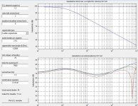
I have made this design where dispersion up to 30 degrees listening angle and up to 20 khz is about equal. Of course, this comes to a price where the frequency respons is less than ideal. However, I'm planning to have active equalization through a miniDSP because of the hybrid system, enabling me to adjust the frequency response to a flat line, whilst keeping the advantage of wide dispersion.
Is this a real possibility or am I mistaken? Sorry if it's an stupid question, just a newbie here.
I'm currently designing a hybrid ESL with the help of a software tool thats floating around on the web, made by a Dutchman whose name I regrettably cannot retrieve. It's a simulation of dispersion and frequency response of a flat ESL panel, plotted for different listening angles. I'm sure most of you are familiar with the program.
I have made this design where dispersion up to 30 degrees listening angle and up to 20 khz is about equal. Of course, this comes to a price where the frequency respons is less than ideal. However, I'm planning to have active equalization through a miniDSP because of the hybrid system, enabling me to adjust the frequency response to a flat line, whilst keeping the advantage of wide dispersion.
Is this a real possibility or am I mistaken? Sorry if it's an stupid question, just a newbie here.
Attachments
Hi,
Perhaps it's a real possibility as ESL_seg seems to be quite good approximation to real word figures.
However you are trading lots of sensitivity for that.
Some beaming control is required but I think in your case it's too extreme") .
.
Second, making the dispersion too wide can bring a lot of room reflections into listening position whats not good either.
Also the wires could be closer to each other, that would result in more field strength and D/S spacing could perhaps be reduced if the construction is accurate enough.
Regards,
Lukas.
Perhaps it's a real possibility as ESL_seg seems to be quite good approximation to real word figures.
However you are trading lots of sensitivity for that.
Some beaming control is required but I think in your case it's too extreme
.Second, making the dispersion too wide can bring a lot of room reflections into listening position whats not good either.
Also the wires could be closer to each other, that would result in more field strength and D/S spacing could perhaps be reduced if the construction is accurate enough.
Regards,
Lukas.
I am in process of such a build and you can find the details here,
A Segmented Stator Desktop ESL
All I have left to do is mount a diaphragm as messing with a epoxy is not fun.
And Lately I have been going over transformer design for the system.
I have many pictures of simulations in that thread so it will be interesting to see how accurate they are.
In order to flatten out your curve you will need more segments.
I have created simulations with a similar curve that you have shown keeping in mind the possibility of using active filtering to flatten it out completely.
This would greatly reduce the power requirements of the resistors.
Those simulations can be found in this thread here,
http://www.diyaudio.com/forums/plan...tor-esl-simulator-esl_seg_ui.html#post2908293
As with any ESL you want to base your design on the highest SPL at the lowest frequency of operation since they have a rising response 6db per octave.
My last panel used window screen as the stator and this worked very good as far as the overall field strength.
My new build is using some .0625" TIG rod and by the time I got it coated it is closer to .080 Dia. now.
The next version will use some thinner .030" to .045" rod as this will help to increase my field concentration slightly.
I don't that it is going to make very much of a difference running a bias voltage of 7.5kv and above, as 13.5KV is the highest I can go with my current supply anyhow.
The hardest thing to do is to make a stator coating that can contain such voltages in such a small D/S of .060" to.090".
It takes at least 6 to 8 mil of coating thickness so you have to add this to your rod diameter to get your spacing.
Remember some coatings are better than others I have been getting about 1500v (and as high as 1900 or 2100) per mil using Rustoleum 2X Clear spray enamel.
it is very hard to get extremely accurate spacings less than about +/- 10 mil of tolerance but I have gotten within this or better with my current build.
It is good to see a new build of similar design rather than just sticking two perforated metal panels together !!! He,he,he,he
I am trying to get as much as +/- 60 degrees of dispersion with my panels as they are for nearfield use.
I would have to agree with Bazukaz that +/- 30 degrees should be ample for a large system used in the farfield.
This would depend mostly on the dimensions of your room.
For example my room is 10.5' X 18.5' and my speakers are aimed along its 18.5' length leaving only 7' between each stack of speakers.
In this case a narrower +/- 15 to 10 degree dispersion would be more desirable as the left and right higher frequency's become reversed by the time they reach my listening position at 14 to 16 feet away with my common Dynamic drivers.
Leaving me with a very smeared stereo image.
This is would be much different if I were in a wider room.
On my last panel with a 3.25" wide diaphragm I have clipped the diaphragm in to the stator at below 300Hz to 220hz with a D/S of about .072 but it was quite very loud, and, increasing the D/S by another 10 to 20 mil solved that issue although it took more voltage to make up the difference in sensitivity.
The resonance of the panel was about 70Hz to 90Hz depending on the tension using .25mil mylar.
I had detected this by using a microphone and it was backed way off of the panel so it wasn't the microphone that was flat topping the signal or the amplifier and you could hear it as well.
I didn't have an SPL meter at the time but it was loud enough to want me to leave the room and I like it loud !!! He,he,he
I was running about 6.5KV of bias at the time and I don't remember the exact transformation ratio but it was around 1:200 or so.
Keep on DIYing !!!
Cheers!!
jer
Hi again,
Basically geraldfryjr is correct, you need more segments to improve SPL.
I went as far as making 24 segments for 30 cm wide panel but perhaps thats not really necessary.
If you are aiming for high dispersion a narrow element(10 cm or so) can do the best; could be mounted on some kind of flat baffle to improve low-midrange response.
Even without optimized segmentation it can give dispersion wide enough.
Instead of making stators from bare metal which is extremely difficult to reliably insulate(even for small panels) you can use PVC insulated wire like PV-3. While it may be rated at 500V or so for mains, the actual breakdown voltage of 0.7mm thick PVC insulation can be thousands of volts(one manufacturer I know of tests at 2.5 kV but IMO it should handle a lot more).
It must be single stranded for stability reasons.
By the way, bias of 7500V for a 2 mm gap may be too high depending on how leaky your panels are.It may work, but take in mind you can end up with corona/clicking noises or membrane collapsing into the stator. Exceeding bias voltage of about 2kV/mm can become tricky, especially for diaphragm stability and reliability.
Edit : it's important to use high voltage metal film resistors for segments. Basically it's best to model the panel with lets say LTSpice and see what kind of voltages they need to handle. You may end up with a requirement of about 1-2 kV per resistor depending on many factors.
Some resistors(carbon composition is the worst) start to distort or even fail when their voltage rating is exceeded which is about 200-300V for regular carbon films.
Regards,
Lukas.
Lukas.
Last edited:
Thanks for your extensive replies. So I understand that active filters to overcome a curved frequency response could be possible, with some drawbacks. I am wondering though if a 5-10 db difference in frequency response could easily be overcome by a system like miniDSP without distortion problems. Anyone got a thought on that?
Thanks for your extensive replies. So I understand that active filters to overcome a curved frequency response could be possible, with some drawbacks. I am wondering though if a 5-10 db difference in frequency response could easily be overcome by a system like miniDSP without distortion problems. Anyone got a thought on that?
I am using miniDSP with ESLs and it works well. DSP cannot correct long decay of diaphragm resonances and polar response.
The distortion can arise if you increase SPL too much in critical regions due to amp/or DSP clipping.
Your model is around 70db/2.83V efficient on average even with very high bias; in my opinion its far too low. If you try to combine with a woofer having sensitivity of 85db it would need a 10-20db boost. That translates to panel requiring 5-6x the voltage. Probability of clipping at either DSP or amplifier output is high indeed, depending on crossover point.
The target is to get as flat(in terms of FR) and efficient panel as practical and apply less electronic EQ IMO.
Some people point out beaming as a significant problem of ESLs; I think it's only so with wide, non-segmented panels.
And if you build a segmented wire panel its easy to re-solder resistors and try different configurations.
Regards,
Lukas.
Last edited:
Hello jeronimo83,
A few comments conerning segmented wire stators:
1) Wire Spacing:
For best uniform electrostatic field, do no space your wires further apart than 2x the diaphragm-to-stator(D/S) spacing.
2) Bias Voltage:
For reasons Bazukaz explained, the bias voltage will be limited to a maximum of about 2kV x D/S(mm).
For example, for D/S=2mm, set Bias Voltage=4kV.
3) Dispersion vs Efficiency vs Flat response:
With ESLs, efficiency is the name of the game. You need to get as much output for a given area as possible. A panel that has very wide dispersion but doesn't play loud enough to listen properly to music is not useful. At a minimum, aim for 80dB. A panel that needs large amounts of equalization for a flat response uses up your amplifier headroom.
For a useful flat response, a minimum of 3 sections are needed...a good starting point for experimentation.
See attached example for a panel similar in size to the one you posted.
.
Attachments
Dispersion is physical property of transducer. EQ will not change this.
This is true for a uniformly driven transducer, but segmented ESLs are not uniformly driven.
You can modify the dispersion and EQ characteristics by progressively filtering out high frequencies as progressively more area of the panel is driven.
Looks like the original source for the matlab tool, http://www.edohulsebos.nl, is no longer available.
You can download an English Translation version from the esl_seg_ui thread Segmented Wire Stator ESL simulator (esl_seg_ui).
- See Post#39 and Post#75 for English Translation version of esl_seg_ui posted by Bazukaz.
You can download an English Translation version from the esl_seg_ui thread Segmented Wire Stator ESL simulator (esl_seg_ui).
- See Post#39 and Post#75 for English Translation version of esl_seg_ui posted by Bazukaz.
- Status
- This old topic is closed. If you want to reopen this topic, contact a moderator using the "Report Post" button.
- Home
- Loudspeakers
- Planars & Exotics
- Wide dispersion by active equalization in a flat (wire) ESL