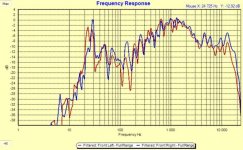
I have a Audiostatic DCM. I bought it some years ago, and have often asked my self what I was thinking. You can hear that there are some qualities, but overall sound is rubbish to be honest. When I started measure, I could understand why. Tried digital correction without too much luck. Then, when I looked at it, it seemed like some baffle step filters might help:
Attachments
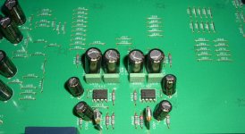
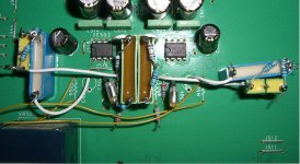
I had a old Rotel preamp laying around, who I started to modify.
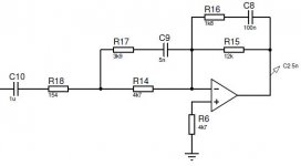
C9 consist of two 10nF capacitors in series, this makes me able so easily change C9 value between 5nF and 10 nF. 5n gives the lowest dip, while 10 gives a lower center frequency.
C9 consist of two 10nF capacitors in series, this makes me able so easily change C9 value between 5nF and 10 nF. 5n gives the lowest dip, while 10 gives a lower center frequency.
Attachments
Last edited:
I have a Audiostatic DCM. I bought it some years ago, and have often asked my self what I was thinking. You can hear that there are some qualities, but overall sound is rubbish to be honest. When I started measure, I could understand why. Tried digital correction without too much luck. Then, when I looked at it, it seemed like some baffle step filters might help:
Audiostatics also produced esl with the so called 'mirror drive' which boost the response below 300 HZ. They sound a lot better imho compared with the models without mirrordrive. Technically it is possible to change the esl to mirrordrive by adding an additional transformer. Mid/high can be modified by its segmentation.
So you might be able to avoid any external filters.
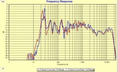
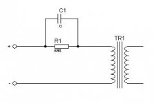
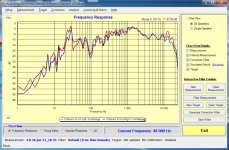
I remember opening the speaker once, and spotted a resistor in series with signal transformer. I suspected this was to increase response around Fs, to give a false impression of more low end. So I opened speaker and shorted the RC filter inside. This actually rised response at high frequency, while there were no effect at mid and low freq. Red is original and blue is modified with only a 6R8 or nothing at all. As you can see, capacitor inside speaker gives a small rise after 5kHz. If you are to use an active filter, I do think you would benefit from bypassing filter.
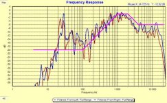
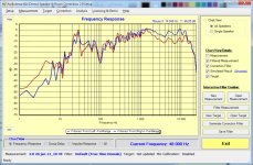
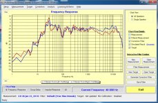
With active filter it gets even better. I'm not very experienced in measuring, have one measurement where it looks even better, but I'm not sure if this is valid.
With active filter it gets even better. I'm not very experienced in measuring, have one measurement where it looks even better, but I'm not sure if this is valid.
Attachments
Last edited:
Audiostatics also produced esl with the so called 'mirror drive' which boost the response below 300 HZ. They sound a lot better imho compared with the models without mirrordrive. Technically it is possible to change the esl to mirrordrive by adding an additional transformer. Mid/high can be modified by its segmentation.
So you might be able to avoid any external filters.
OK, thanks for the tip. Is it possible to obtain any info about how to do this on this older model, and with some measurements to verify?
By the way, tested input impedance by applying a voltage with a signal generator and measure voltage before and after a series resistor of 6,8R. Already at 2Hz impedance was close to 8 ohm, dispute DC resistance of approx. 0,5ohm. So if your amp doesn't put too much DC at terminals, or is very weak, it should be fine to bypass filter.
I have Audiostatic and feel your pain.
After intensive mods, mine started to really shine and I wouln't let them go anytime soon.
They put a some expensive system to shame.
1- Audiostatic do not use damping behing the mylar and it's very bad.
Acoustat used a kind of 3/8 thick felt pad glued behind stator.
I think Quad did the same but not 100% sure what it was.
I used foam (maybe one day I'll try felt but I had foam around) to cover maybe 70% of the back. I just used pressure fit (no glue or anything)
It help the sound quite a bit.
2-For the dropping response, building wings on both side help tremendously too.
More weight, less vibration from panel and lower rolloff.
My U baffle audiostatic have 12" wing on each side with felt and I used few bracing too.
Impressively, high benefited very much from the side wings.
3-The input resistor in your static is 6.8ohms, mine was factory 2.2 ohms.
I use 0.22ohms now (as a fuse) for a little more spark on the top but still fall short on the 20khz...
I just started to experiment with a supertweeter but still in early stage of experimentation
4-Feets are important too.
I used to use nothing for the worst (concrete floor covered in linoleum)
Spike are a bit better but not much
Soft hockey puck are very good.
I use superball (stupid high bouncing ball from dollarstore) cut in half to do the feets
3 per side and theses feets are yet to be beaten in my system...
I've tried some more feets but nothing sonicaly worth mentionning.
5-For bass, do not dream, you need a sub.
I cross mine at 100hz and do only use a capacitor on the amplifier input.
My subs are much better moving air than the smallish mylar running out of excursion...
6- a bit more hardcore but the audiostatic are segregated panel. Kind of 2 ways if you wish. Method and resistor value seem to change from version to version. I redid mine in 3 parts instead of 2 and got much better (more even) frequency response.
http://www.diyaudio.com/forums/planars-exotics/227349-raal-supertweeter.html
Martin
Quote: Acoustat used a kind of 3/8 thick felt pad glued behind stator.
Acoustat only used these felt pads because the diaphragm material that they used DuPont HS65 was heat shrunk to tension and was unable to generate quite enough tension for the s/d spacing and the width of the panel used. The felt added enough resistive air load to help stabilize the panel. With sufficient tension these pads are not necessary. Best regards Moray James.
Acoustat only used these felt pads because the diaphragm material that they used DuPont HS65 was heat shrunk to tension and was unable to generate quite enough tension for the s/d spacing and the width of the panel used. The felt added enough resistive air load to help stabilize the panel. With sufficient tension these pads are not necessary. Best regards Moray James.
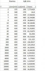
Found the reason why removal of resistor increased output at higher frequencies. Reason is of course that impedance start decreasing after a certain point, then goes to a minimum value of 3,3ohm just above 10kHz. Here are the values if it should be of any interest, sorry for the big hole between 400 - 2000Hz.
Attachments
Hi,
Audiostatic had the Bass Boost technique patented. They used a autotransformer with two inputs, one for feeding Bass and one for feeding MH. The inputs were joineded together via coupling parts that shaped amplitude response such that bass got a boost. As every other detail in the construction, the quality of the audio transformer as well as the auto transformer was poor and cheap. The audio transformers hardly reached the quality of standard EI-core power trannies as you can see from any impedance plots (impedance minimum around just 10kHz with a segmented panel!). See US Patent 4,461,931 for the auto transformer patent.
jauu
Calvin
Last edited:
Compared to audiostatics without mirror drive, audiostatics with mirror drive have a far more convincing bass response. The mirrodrive starts below 300 Hz so it soe more than only producing the deepest bass notes. It lifts the upper bass as well, adding some warmth. My small ES200 beats the much larger es500 regarding deep bass. Ok, I did some mods like replacing all the old and cheapy caps, changing the segmentation, mylar, damping of mylar.
In my opinion the audiostatic without mirror drive have a hollow unpleasant sound which is more or less obvious depending on the acoustics of your room and your musical taste.
The very large es500 performed better but still lacked the deep bass.
There is some debate on the dutch forum whether you should replace the audiotransformers (autotransformer of the mirror drive is hard to get I suppose). I reckon that Calvin is right in his statement that the audiotransformers are not the best. I have reduced the high frequency section so dispersion improves and the transformers will see an easier load as a consequence.
Now the sound may be not perfect but it is very satisfying.
Audiostatics without mirror drive will benefit from wings. I have experimented with wings as well. It does not generate the very low push of the mirrordrive but it makes the overall sound warmer. Panel vibrations were killed as well (a major problem with es100). Unfortunately my wings were very ugly.
Hi,
..as you can see from any impedance plots (impedance minimum around just 10kHz with a segmented panel!).
Calvin
Could you explain this in more detail? What is a segmented panel, and why is minimum Z at 10kHz bad on a segmented panel? Some nice links would do
") My knowledge is limited.
My knowledge is limited.As far as I know, wings and baffle step filter does more or less the same thing, except from slightly reduced sound pressure with filter. Looks betterAudiostatics without mirror drive will benefit from wings. I have experimented with wings as well. It does not generate the very low push of the mirrordrive but it makes the overall sound warmer. Panel vibrations were killed as well (a major problem with es100). Unfortunately my wings were very ugly.
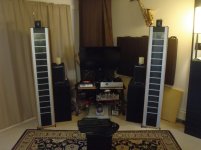
I can't stress enough to add wing on your audiostatic.
And like Dijkstra mention, the result is very ugly.
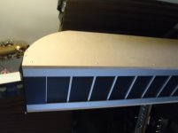
Here a picture of mine (yet to have veneer on side)
Even better would be to use a Infinite baffle if you can.
I used that around my acoustat 2+2 years ago and had a f3 of about 25 without any sub!!!
That was clean bass too, unfortunaly, I can't do it again where I live now.
Forgot to mention to seek for a choke mod (google it, It was Morray James idea)
It is quite a worthy mod.
I use a 14Henry on my audiostatic (2 7henry in serie)
Before somebody said, I always use a blanket over my tv screen before listening music.
Android remote control are awesome
Martin
And like Dijkstra mention, the result is very ugly.
Here a picture of mine (yet to have veneer on side)
Even better would be to use a Infinite baffle if you can.
I used that around my acoustat 2+2 years ago and had a f3 of about 25 without any sub!!!
That was clean bass too, unfortunaly, I can't do it again where I live now.
Forgot to mention to seek for a choke mod (google it, It was Morray James idea)
It is quite a worthy mod.
I use a 14Henry on my audiostatic (2 7henry in serie)
Before somebody said, I always use a blanket over my tv screen before listening music.
Android remote control are awesome
Martin
Attachments
Last edited:
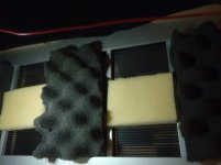
Do you mean 40/50Hz? My is at right below 30Hz. To me it seems like you are introducing a flow resistance who are dampening excursion of membrane, is that the function of your mod?one more pic of the back of the panel
Foams just barely holds there but provide critical damping.
My 40h peak got reduced quite a bit
(your seem to be at 50h)
I will consider to try large baffles, it might be possible for me to do if I'm a bit creative, but I'm not sure.
Could you explain this in more detail? What is a segmented panel, and why is minimum Z at 10kHz bad on a segmented panel?
A segmented panel does not connect all of the panel area directly to the transformer. Rather it uses resistors to segment the panel area so only a small area is directly driven by the transformer at high frequencies(HF). This is important because the panel capacitance will limit the HF bandwidth due to an underdamped low-pass filter formed with the transformer leakage inductance. The Audiostatics are 2 segment designs.
The minimum Z point indicates the frequency where the response of the transformer will start to roll off.
In general you would like this to be >20Khz, but even 15kHz is useable.
For example:
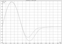
Attachment #1: shows a model for the impedance and transformer response for Audiostatic ES-100. The resonance between transformer leakage inductance(LL) and panel capacitance can be seen by the minimum dip in impedance at 13,669Hz. You can see that this corresponds with the roll off point of the HF response of the transformer.
Attachment #2: shows what would happen if the whole panel was hooked up to the transformer without segmentation.
Resonance is moved down to 7,671Hz as is the HF roll off point.
Attachment #3: using the model we can compare the response for different values of resistors and capacitors in the primary circuit. You can see that the transformer response changes match pretty well the differences you measured.
In general, increased resistance dampens the resonance and rolls off the response. Adding a capacitor in parallel with the resistor can help to reduce the roll off or peak the response above the resonance point when a larger resistance value is used.
If anybody would like to play around with the modeling tool, let me know and I can post the Excel spreadsheet.
Attachments

I would Like to have the spreadsheet
Do yo know if the es100 used the same transformer as the wing?
Email it to me.
mapoulin@gmail.com
Do yo know if the es100 used the same transformer as the wing?
Email it to me.
mapoulin@gmail.com
Here some measurements i made about Audiostatic transformers (with different loads)
Also a measurement from core saturation. Everybody can see that AS has a problem with core saturation which will be even greater when a mirrordrive will be added.
Also a measurement from core saturation. Everybody can see that AS has a problem with core saturation which will be even greater when a mirrordrive will be added.
An externally hosted image should be here but it was not working when we last tested it.
An externally hosted image should be here but it was not working when we last tested it.
Here some measurements i made about Audiostatic transformers (with different loads)
Also a measurement from core saturation. Everybody can see that AS has a problem with core saturation which will be even greater when a mirrordrive will be added.
Thanks for sharing the measurements. I agree that the AS transformers did not have the best power handling capability. Perhaps that is one of the reasons they put the higher resistance values in series with the primary. I posted brief summary of my test results for the mirror drive on an ES-300RS here:
http://www.diyaudio.com/forums/plan...c-es-100-mylar-replacement-2.html#post2061070
Looking at the measurements for various loads on your AS transformers, it looks very similar to what I would predict if using transformer parameters for the transformers on an older ES-100 I measured. The older transformers had higher leakage inductance, but lower winding capacitance.
Attachment #1: shows the transformer parameters I had measured.
Attachment #2: shows predictions for the loadings you measured.
@ etalon90,
I do not know how the transformers for the Wing compare to the ES100.
My guess is that they are similar since the panel dimensions are similar, but probably not identical.
I will get a copy of the spreadsheet emailed to you tonight.
Attachments
- Status
- This old topic is closed. If you want to reopen this topic, contact a moderator using the "Report Post" button.
- Home
- Loudspeakers
- Planars & Exotics
- Audiostatic baffle step filter