A segmented panel does not connect all of the panel area directly to the transformer. Rather it uses resistors to segment the panel area so only a small area is directly driven by the transformer at high frequencies(HF). This is important because the panel capacitance will limit the HF bandwidth due to an underdamped low-pass filter formed with the transformer leakage inductance. The Audiostatics are 2 segment designs.
The minimum Z point indicates the frequency where the response of the transformer will start to roll off.
In general you would like this to be >20Khz, but even 15kHz is useable.
For example:
Attachment #1: shows a model for the impedance and transformer response for Audiostatic ES-100. The resonance between transformer leakage inductance(LL) and panel capacitance can be seen by the minimum dip in impedance at 13,669Hz. You can see that this corresponds with the roll off point of the HF response of the transformer.
Attachment #2: shows what would happen if the whole panel was hooked up to the transformer without segmentation.
Resonance is moved down to 7,671Hz as is the HF roll off point.
Attachment #3: using the model we can compare the response for different values of resistors and capacitors in the primary circuit. You can see that the transformer response changes match pretty well the differences you measured.
In general, increased resistance dampens the resonance and rolls off the response. Adding a capacitor in parallel with the resistor can help to reduce the roll off or peak the response above the resonance point when a larger resistance value is used.
If anybody would like to play around with the modeling tool, let me know and I can post the Excel spreadsheet.
Excellent folks, thank you very much!
@esltransformer: Is it possible to get an uprated transformer? As far as I can see, it's used plated transformers, is it uncommon to use ferrite core? I'd think this would possibly improve HF response...? Pardon any ignorance, transformers are not my specialty...
A transformer as I made for myself is not a real "upgrade" for a Audiostatic.
My transformer is much better then the original AS so it's not plug&play. You have to change the segmentation, less wires for the middle section and maybe different resistors too. Also the serieresistor should be changed in a much lower value.
Ferrites are not suitable for audio frequencies, the benefits for ferrite is for f>100kHz
What material audiostatic horizontal strips which support wires are made of ?
The Audiostatic horizontal supports are made from aluminum. In my experience, it is not desireable to use metal for wire supports when building segmented stators. The reason is that there will be capacitive coupling from segment to segment throught the metal supports that bypass the segmentation resistors. So, high frequencies are not filtered out from the segments further from the center of the panel like you might think just looking at the schematic. Dispersion suffers compared to a panel made with non-conductive wire supports.
The Audiostatic horizontal supports are made from aluminum. In my experience, it is not desireable to use metal for wire supports when building segmented stators. The reason is that there will be capacitive coupling from segment to segment throught the metal supports that bypass the segmentation resistors. So, high frequencies are not filtered out from the segments further from the center of the panel like you might think just looking at the schematic. Dispersion suffers compared to a panel made with non-conductive wire supports.
Thanks. I suspected that it's from aluminium from some pictures.
It's quite strange why they used such a material. I have not thought about capacitive coupling causing segmentation resistors be bypassed
") . IMO it's not the safest way to build stators as there is still a possibility of wire insulation breakdowns or even mechanical damage.
. IMO it's not the safest way to build stators as there is still a possibility of wire insulation breakdowns or even mechanical damage.Lukas.
Last edited:
Thanks. I suspected that it's from aluminium from some pictures.
It's quite strange why they used such a material.
It probably comes down to trade-offs between (structural stiffness vs size) and (material cost vs labor cost).
Aluminum(6061) is 10 - 20 times stiffer than plastics of same size so you can build thinner stator frames with aluminum.
This would be especially important when the cross bars need to span 30cm wide panels like the ES-500.
Also, Aluminum is stable where as most plastics can/do warp over time.
Aluminum may cost more, but it can be purchased in various stock shapes/sizes that can be used as is without any additional labor.
Use of plastics usually involves the need to cut smooth, straight cross bars to size from sheets of material.
This may not be important for DIY, but could be driving factor for a manufacturer.
Last edited:
Well I think optics was perhaps a factor to use aluminum.
Currently I am not a big fan of open stators mainly due to attraction of dust.
Have been fighting to make the speakers free of buzzing noises while doing sine sweeps for months and it looks like I am finally getting acceptable results. But that includes some protection of dust, at least a light, semi-transparent synthetic cloth.
Regards,
Lukas.
Hi,
after my experience with aluminum frames like Audiostatic (pics of those on my website) the capacitive coupling doesn't play any significant role here.
If You want to design a 'open' stator, the redish card board often used for the inner frame structure is out. Some black plastics or transparent acrylics may be left. But those materials may have stability and strength and fixing issues. The aluminum bars are standard off of the shelf products available in any DIY store here in Germany either as square hollow tube or massive rod or in rectangular shapes. They have a good looking anodized surface, are stiff enough even for wide panels, can be easily sourced and glued. One needs to watch if the glue is agressive to the wire insulation which over time could result in leakage or even breakdown. Plastic bars may not stick well with non-aggressive glues. With aluminum bars one may even use simple waterbased household glues to fix the wires. A cheap, easy to use and reliable solution ... and very DIY
I've used hollow square of 10x10mm shape and massive 2x10mm shape in several panels successfully.
Panels are working well even after 20 years. So far the only thing I noticed every now and then is, that the metal bars aquire a bit of charge over time, that faintly zapps you on touching them. But the zap is even less than what happens walking over a carpet.
jauu
Calvin
Hi,
Perhaps it depends a lot on specific implementation.
Here is some calculations I have carried out by using various calculators :
Assumptions :
1) Supporting strip is 10x10mm
2) Count of supporting strips : 20 per stator
3) Wire diameter 2mm, PVC insulatation thichness 0.6 mm.
Assume a simplification : this acts like 1mm wide conductor, 0.6mm insulator, k(PVC) = 4.
4) Wire sections : 24+12+6+12+24
It turns out that each wire can have about 0.6 pF capacitance to one supporting strip(simplification, but perhaps conservative due to assumptions in 3).
a) Reactance from center wires to supports. Multiply this by number of strips x number of wires and we have a summed capacitance of center segment to all strips :
0.6x6x20 ~= 72 pF.
b) Reactance from next segments to supports uses two times more wires(x2 segments) therefore it's capacitance is 72x2x2 = 288pF.
c) By calculating series capacitance, we have the result.
The first segmentation resistors are bypassed by equivalent capacitance of about 57.6 pF.
The 2-3 segments are bypassed by far larger capacitance of about 230 pF.
It turns out that under these assumptions segmentation resistors are bypassed with significant capacitance which can have even lower reactance than resistance of resistors.
Regards,
Lukas.
Hi,
after my experience with aluminum frames like Audiostatic (pics of those on my website) the capacitive coupling doesn't play any significant role here.
If You want to design a 'open' stator, the redish card board often used for the inner frame structure is out. Some black plastics or transparent acrylics may be left. But those materials may have stability and strength and fixing issues. The aluminum bars are standard off of the shelf products available in any DIY store here in Germany either as square hollow tube or massive rod or in rectangular shapes. They have a good looking anodized surface, are stiff enough even for wide panels, can be easily sourced and glued. One needs to watch if the glue is agressive to the wire insulation which over time could result in leakage or even breakdown. Plastic bars may not stick well with non-aggressive glues. With aluminum bars one may even use simple waterbased household glues to fix the wires. A cheap, easy to use and reliable solution ... and very DIY
I've used hollow square of 10x10mm shape and massive 2x10mm shape in several panels successfully.
Panels are working well even after 20 years. So far the only thing I noticed every now and then is, that the metal bars aquire a bit of charge over time, that faintly zapps you on touching them. But the zap is even less than what happens walking over a carpet.
jauu
Calvin
Maybe Calvin's point it that compared to large unsegmented panels the dispersion is so much better anyways, that worring about coupling thru the crossbars is not that important. I can't argue with that logic. For a given amount of capacitive coupling thru the crossbars, the impact on off-axis response is seen more for designs with lower segment capacitance and higher value of ladder resistors. In general this means it will be more important for FR designs than for hybrids.Perhaps it depends a lot on specific implementation.
Due to fringing between wires and cross bars, you will find capacitance to be 2x to 3x higher than estimated with formula for parallel plate capacitance. Formula for capacitance between wire and plate would be more appropriate. If spacing between the wires is < OD of the wires the capacitance is very near what you would calculate using the segment width in the parallel plate formula. If you have an LCR meter you can easily measure with the ladder resistors removed.It turns out that each wire can have about 0.6 pF capacitance to one supporting strip(simplification, but perhaps conservative due to assumptions in 3).
Don't forget that there will also be coupling directly from 1-3!The 2-3 segments are bypassed by far larger capacitance of about 230 pF.
Trying to model in Spice for more than 3 segments and you wind up with a web of capacitances
Absolutely. As an example, the attached plot shows expected and measured voltage driving the outter segments in an ES-100 style ESL. Measured capactive coupling was about 200pF! The level at which the attenuation flattens out is dictated by the capacitive voltage divider made from the segment capacitance and the coupling capacitance. This amount of response from the outer panels for f>10Khz negatively impacted the off-axis response. Remember plot shows electrical signal applied(not SPL) to outter segments which are larger in area than the center segment.It turns out that under these assumptions segmentation resistors are bypassed with significant capacitance which can have even lower reactance than resistance of resistors.
The charge you mention is the static charge stored in the (wire-pvc-crossbar) capacitor that Bazukas described. The HV supply connections to this capacitor are thru direct connection to wires, and surface leakage path from diaphragm contact to the crossbars.Panels are working well even after 20 years. So far the only thing I noticed every now and then is, that the metal bars aquire a bit of charge over time, that faintly zapps you on touching them. But the zap is even less than what happens walking over a carpet.
If you try grounding the crossbars to avoid the charge buildup you will notice two things:
1) Increased capacitive load on the step-up transformer since it now has to drive this capacitance in parallel with the stator-to-stator capacitance.
2) If you are using a QUAD style neon light charge indicator, the flash rate will increase from current thru the grounded leakage path. This is most noticeable when connecting and disconnecting the grounding wire on humid days.
Attachments
Last edited:
As you can see in the first post, there is a big resonance at approx 30Hz. Is it any way to modify the system to get rid of this?
The diaphragm resonance is most easily damped by application of acoustic resistance to one or both of the stators in the form of silk screen mesh or thin felt.
This will ruin the see thru optics of the ESL panel(this is very important to some people), but the bass response is much improved.
I posted some measurements of this damping technique here:
http://www.diyaudio.com/forums/plan...con-dots-resonance-control-3.html#post1958582
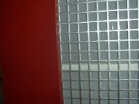
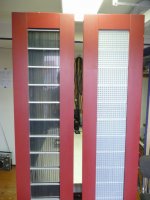
There had been a thread on another forum detailing the application of silk screen mesh damping to an ES-100. But it looks like the link no longer works. Attached are two pics I had saved from the posting before it disappeared. You can see that they glued silk screen mesh to a perforated metal sheet with square openings and then mounted it behind the rear stator.
Forum posting(link appears dead now): http://forum.puresound.be/viewtopic.php?f=9&t=447
Company that did the work: Modificatie Audiostatic door Audio 4 elektrostaten
One other alternative is to place on electronic notch filter in line between your preamp and power amplifier.
Attachments
Maybe this link will help to
http://www.wiremeshok.com/Polyester-screen-printing-mesh.htm
mesh 195 (inch) or 77(metic) will be probably good
http://www.wiremeshok.com/Polyester-screen-printing-mesh.htm
mesh 195 (inch) or 77(metic) will be probably good
The diaphragm resonance is most easily damped by application of acoustic resistance to one or both of the stators in the form of silk screen mesh or thin felt.
This will ruin the see thru optics of the ESL panel(this is very important to some people), but the bass response is much improved.
I posted some measurements of this damping technique here:
http://www.diyaudio.com/forums/plan...con-dots-resonance-control-3.html#post1958582
There had been a thread on another forum detailing the application of silk screen mesh damping to an ES-100. But it looks like the link no longer works. Attached are two pics I had saved from the posting before it disappeared. You can see that they glued silk screen mesh to a perforated metal sheet with square openings and then mounted it behind the rear stator.
Forum posting(link appears dead now): http://forum.puresound.be/viewtopic.php?f=9&t=447
Company that did the work: Modificatie Audiostatic door Audio 4 elektrostaten
One other alternative is to place on electronic notch filter in line between your preamp and power amplifier.
Last edited:
That's really ugly.... try plastic U profile.
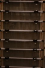
Here is another idea how silkscreen mesh can be fixed to a wire stator with paper clips.
The metal handles of each clip are removed after.
That's really ugly.... try plastic U profile.
Why? The speaker is covered with cloth, and damping is on the rear side. Paper clips are good for experimentation - easy to remove and hold well.
Ok, just for a quick experiment it will do.
The tighter and closer the mesh is to the foil the better it works.
Alfer* deliver U profiles which exactly fit the Audiostatic aluminum rods.
*available at Hornbach (German and Netherlands)
The tighter and closer the mesh is to the foil the better it works.
Alfer* deliver U profiles which exactly fit the Audiostatic aluminum rods.
*available at Hornbach (German and Netherlands)
Why? The speaker is covered with cloth, and damping is on the rear side. Paper clips are good for experimentation - easy to remove and hold well.
I would have believed that a cloth would damp higher frequencies?
If so, one alternative would be to just add on backside. If it influence on higher freq, it will also influence on spread pattern, but for all we know it might improve interaction between speaker and room.
I can implement a notch filter, but in general, I believe in "making right from the start" to get the best sound quality.
Brilliant idea regarding the paper clips. We have exactly the same type at work
Really appreciate your input guys!
Last edited:
- Status
- This old topic is closed. If you want to reopen this topic, contact a moderator using the "Report Post" button.
- Home
- Loudspeakers
- Planars & Exotics
- Audiostatic baffle step filter