Wow thx for the so long rePly and help , so in the end , they suckwell at least a good reason to buy some new ones
Have you check the bias or have you not??
Before jumping to conclusions, you should confirm the core material is actually the cause of your problems, otherwise you could spend money for nothing
Hello Elvee,
Is this the test you propose? (see attachment)
1) With switch open, adjust the output of the preamplifier to a low level that produces audible distortion in the ESL.
2) Close switch to add/mix in a high amplitude ultrasonic signal with the audio going to the power amp.
3) As the amplitude of the ultrasonic signal is increased, the amount of core distortion should decrease resulting in less audio distortion heard in the ESL.
@alexberg,
WrineX has tried several power amplifiers with identical results.
It seems unlikely that all of his power amplifiers have DC offset problems.
.
Attachments
Have you check the bias or have you not??
planning on doing this by laptop, i add a sine wave generator to add a 20K singal while playing music that distort on the esl. but its only to check if this works, i wont like to put up the volume with a 20K tone where the impedance is as low as it gets
or i would fie my amp or just goes in protection i guesi will do this test tomorow when my gf is not home so i can use her laptop
Hello Elvee,
Is this the test you propose? (see attachment)
1) With switch open, adjust the output of the preamplifier to a low level that produces audible distortion in the ESL.
2) Close switch to add/mix in a high amplitude ultrasonic signal with the audio going to the power amp.
3) As the amplitude of the ultrasonic signal is increased, the amount of core distortion should decrease resulting in less audio distortion heard in the ESL.
Conceptually, that's it. There are a number of ways of practically implementing it.
Sure, I said in regard to what I saw on pics posted...Hello Elvee,
Is this the test you propose? (see attachment)
@alexberg,
WrineX has tried several power amplifiers with identical results.
It seems unlikely that all of his power amplifiers have DC offset problems.
.
Oh well, even with a crappy 60/50 Hz x-former you won't get "big" distortions @ let's say 500 Hz. The core is not that important at higher frequencies and low amplitudes. What counts is the leakage inductance.
Unless it's a price optimized "special" x-former with low turns count/small core size.
I would of get 100 W 12V halogen lamp dirt cheap transformer, preferably not a toroidal one and check it again. Very often as others mentioned it's a hidden oscillation of an amp due to complex load - it can "rectify" ac signal manifesting as a DC offset.
As to idea of HF tape recorder type bias - I doubt you can get enough HF component to substantially move a working point on the x-former in question. Even with a small size magnetic head and cross section of a magnetic tape one need up to hundred volts of HF bias
Very often as others mentioned it's a hidden oscillation of an amp due to complex load - it can "rectify" ac signal manifesting as a DC offset.
I guess a few minutes with an analog scope and/or equipment to run an impedance curve would probably shed some light on the issue.
WrineX, any chance you have a friend who could loan you an oscilloscope or help out with some impedance measurements?
I hope so. Would really be nice to know what this unusual distortion is.
Very well could be...still waiting to see a pic and some details on size and core type.Unless it's a price optimized "special" x-former with low turns count/small core size
I was wondering about that...exercising the core capability at HF would take substantial input voltage as you say.As to idea of HF tape recorder type bias - I doubt you can get enough HF component to substantially move a working point on the x-former in question. Even with a small size magnetic head and cross section of a magnetic tape one need up to hundred volts of HF bias
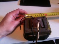
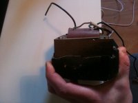
ok so here are 2 pictures of the tranformers. as requested..
the core measures 9.5 cm x 8 and is aprox 2.5 cm thick laminated from 0.5 mm laminates.
they look a bit weird because there cast in some sort of resin wich i cant remove. the baffle of the type of speakers there from was made of this resin so they just did the tranformer in when casting whas not dry yet or even while casting.
and no i dont have anyone with a scope that i know.
Attachments
Last edited:
That's obviously cheap, power transformer grade metal, no surprise it causes distortion. It can create illusion when driven from a low impedance source, but when the value of the magnetizing inductance influences the output voltage, it shows its true colorsok so here are 2 pictures of the tranformers. as requested..
the core measures 9.5 cm x 8 and is aprox 2.5 cm thick laminated from 0.5 mm laminates.
<I was wondering about that...exercising the core capability at HF would take substantial input voltage as you say>
Well, for instance, cassette tape recorder 100 mH head 1.2 mA => 37 V@ 50kHz. You can easily visualize the size of the head and the core inside...
On the other hand let's assume x-former's in question core goes into saturation @ 1.5T & 30 Hz and 20V rms thus 30 kHz additional flux density excursion would be 1.5 milliTesla... @ 20V RMS.
Still I would advise to get 12v/230v halogen lamp x-former or two and check - can be used for intended application later. it's like 5-10 eu on sale.
ok so here are 2 pictures of the tranformers. as requested.
Thanks
Looks to by E96 size laminations which is the same size used by Audiostatic in their ES-100.
As far as the quality of the iron used, that is hard to say from a picture but it does not look at all like the light grey I am used to seeing on quality audio transformer cores. Also, it looks like there is no insulating wax or varnish between the lamination layers. Is that correct? That would certainly result in increased core losses.
What do you mean?
2 cm thick, i mean stacked.. what should one laminate look like ? for an audio tranformer
2 cm thick, i mean stacked.. what should one laminate look like ? for an audio tranformer
The stack height of laminations(2cm) determines the core area, which in part defines how much voltage you can apply at a given frequency before saturating the magnetic material the core is made from. However, the material that the core is made from will define how linear the magnetization curve is, independent of the stack height.
I believe what Elvee was saying was that lamination of 0.5mm thickness are usually only found in power transformers which would mean lower quality, less linear magnetic properties. Laminations made for audio use tend to be thinner than that. The thickest "audio grade" laminations I have seen were about 0.3mm.
Hello Elvee,
Is this the test you propose? (see attachment)
1) With switch open, adjust the output of the preamplifier to a low level that produces audible distortion in the ESL.
2) Close switch to add/mix in a high amplitude ultrasonic signal with the audio going to the power amp.
3) As the amplitude of the ultrasonic signal is increased, the amount of core distortion should decrease resulting in less audio distortion heard in the ESL.
@alexberg,
WrineX has tried several power amplifiers with identical results.
It seems unlikely that all of his power amplifiers have DC offset problems.
.
sorry to bring back a very old post, but since i got again the same problems with different panels but same amplifier,same High voltage cascade and same tranies. Also tested with a new transformer (T300), from audio 4 , a person that makes tranformers as upgrade. (same result so trannies should be ok)
The problem
If i listen without the 20 K tone on and i add volume the sound is really tiny and distorted then there is a certain point almost like fliping a switch where the sound breaks lose undertones are filled in again and it does not sound distorted
i did the test with the test tone, since i can only put out 20Khz on the laptop i was limited. with the 20k tone on, it did sounded less strained, like what happended when i just increased the total volume. it sort of opens up, when the 20K is added lows get fuller again (weird but true).
Still not completely gone.
Does this indicate DC offset of the amplifier? or could there be another thing causing the same problem ? because as mentioned i tried 3 amps, back then One rotel, one class A Stemvoort, and the pioneer reference.
would be a lot out of the lotery to have 3 amps with Dc offset? (sold 2 to already)
like a normal cap used in crossover ? but then huge ? hmm what about the actual crossover cap where does that one go.
The larger the better. Voltage drop across the cap should be low to avoid distortion from trafo. IMO 4700u@63v isnt too much. Even polarized could be used for testing, often theres not particularly big difference between polar and non polar.
- Status
- This old topic is closed. If you want to reopen this topic, contact a moderator using the "Report Post" button.
- Home
- Loudspeakers
- Planars & Exotics
- distortion From ESL at low level