Has anyone done test with Antek Tranfourmers with a passive crossover are any crossover in line??....say sets at 250-300hz upslop??...
Or are these test done full rang.
I know this may have been ask alredy...some where...
Thanks for any an all info on ESLs
I've only done listening tests, not measurements, with the Antek An-506 tandem setup crossed over at 225Hz & 24db/oct slope using an active crossover upstream of the power amp. I assumed they would not be suitable for full range operation. I can only attest that they sound really good when crossed as I described.
Has anyone done test with Antek Tranfourmers with a passive crossover are any crossover in line??....say sets at 250-300hz upslop??...
Or are these test done full rang.
Hello tyu,
I did try a 300 Hz passive 2nd order crossover with the Antek and it worked well, no signs of core related distortion.
This is the panel crossover setup i am use now.....this come from ML. Do you think i can setup the Antek AN-0506 this way.
You could use two Antek's to do something similar, but the step-up ratio would only be about half of the ML transformer.
I redrew you crossover in Figure (A) Did I get it correct?
Can you tell me what ML model this is for?
All of the ML crossovers I have seen or worked on included an inductor across whole or part of the primary as shown in Figure (B) & (C) to provide a stable inductance for the high-pass crossover to work with. Sometimes there was a resistor in series with the inductor.
Does your crossover have such an inductor?
Thanks for sharing this ML info.
Attachments
Last edited:
Thanks for your Art...Bolsterst
You have the SL3 crossover if not go to the MLC site you can get most All ML there.
With the crossover in the SL3 an the Ascent,Ascent i,thay put a induckter in,2.5mh in the center tap to the Neg input, in,the SL3 there is a 1ohm 20watt.
The Acent,i thay went to the just the induckter,2.5mh to ground.
In the Re-Qust, Odyssey, Proidgy thay went to the crossover input on the center tap.
As you know i have been working with all the logans i have had,from The Aerius, SL3,CLS, Ascent,i,Proidgy....two pr own some.
What I would like to know if you can tell me,if the induckter is ran to the neg input only then to the centap. it like i get more output, or is it just ezer for the amp too drive??.... With nothing on any of the center taps of the prmary side of the stepup Xfourmer thay sound Great ...but it takes more power to drive them.
But my lov of the sound of a 60watt tube amps wont drive them, so i set them up with a switch, so when i use sand amps i can pull the center tap off the neg input... on The SL3 an the Acents,an others the swetch is all ready there it was for the base drop...-3db.. i never used this
If a 1ohm res.an the induckter is added, like in the SL3 centap, it sound diff,Not better...well to me.
I have put the Ascent crossover in the SL3s, where it put the 30mf cap in front of the 3ea.3ohm res. This get the fullrang from hiting the res.frist an can case ringing , Sounds sweeter,a littel more forgiving.I like it a lot,other may find this a upgread! All the same partes are there in the SL3.you can go back if you dont like.
So do you think the induckter can work as to add inductens to just one of the Antek Xfourmer?
An have you done any Center tap primary crossover setups with setup Xfourmers?
It a funky setup,??
Thay put the input res. to the crossover back in frount ,so thay get hit by fullrang,i dont know if thay did this just so it would sound diff when you did a side by side set,so you would here a diff an pay more $$,same panel size?....i know the woffer are diff. but....
thanks for any an all the info you have on get the best sound out of All ESLs
Last edited:
A. is right...it was a mix i came up with... for the SL3 An Ascent ...the Re-qust an the Odyssey...parts i had on hand. All there tranfourmers are the same but for the re-qust.
The Proidgy uses two pr speaker....like the Xfourmer SL3 an other... i do not get the inducters?? the Sl3s an the Ascent have the inducters on the centap of the primary...i thought it was to set the stepup xfourmers to just use 1/2 the windings...but if i run the center tap to the neg input only...i get less output....?? Can you tell me what adding the 1ohm dose to the inducker...flotet more.. give even more output???
For me on these ML crossover one clools thing i got was the Zobel thay came up with for the Res...Vary cool i never saw that befor an it works great!.....
Thanks
Sorry as you can seeee.... my brain is not wired like others...it setup for 220 an it only geting 110...Maybe........
Last edited:
ML crossover
Had to go to a diff PC....so all can see
Had to go to a diff PC....so all can see
Attachments
Last edited:
Hello tyu,
That's a lot of questions on the ML SL3 crossover. I'll see if I can answer them.
1) What is the purpose of the 2.5mH inductor connected to the CT of the primary?
Looking at Figure (A) you can see that the (2.5mH + 1ohm) is connected across half of the primary turns. By transformer action, the impedance seen by the crossover network will be that of a (10mH + 4ohm) network. In fact Figure (B) is electrically identical and produces the same response and load impedance. It is a common arrangement for ESL hybrid passive crossovers.
So, why did ML bother with the CT loading? Perhaps it comes down to $.
A 2.5mH inductor is cheaper and smaller than a 10mH.
2) Why doesn’t connecting the CT to ground result in higher output?
Figure (C) shows this arrangement. Since the number of primary turns were halved, the step-up ratio would be doubled so it would make sense to expect higher output. But, halving the primary turns reduces the impedance the transformer loads the crossover with by a factor of 4! To get the expected higher output, you would need to change the 1ohm resistor to 0.25ohm, and the 30uF capacitor with a 120uF capacitor. This would give you higher output if your amplifier could handle the resulting impedance that now dips below 1ohm in the midrange.
3) What happens when I remove the 1ohm resistor in series with the 2.5mH going to the CT?
Attachment #2 shows a comparison of response and impedance with and without the 1 ohm resistor. The Blue curve is with the 1 ohm resistor. You can see that removing the resistor boosts the output above the 300Hz crossover by about 3dB. At this same frequency, impedance drops by 2 ohm to just under 4 ohm.
4) What happens when I completely remove the 2.5mH inductor from the circuit?
Figure (D) shows this arrangement. Without any inductor, the load seen by the crossover at lower frequencies is mainly defined by the primary inductance which changes with signal level. In general you will probably be playing the panel lower than the 300Hz crossover, but will not have the proper equalization above crossover.
5) Can the Antek transformers by used with the SL3 crossover?
Yes, if you use Figure (B) you would have nearly the same step-up ratio and response as ML.
Of course you would probably need to tweak component values to compensate for differences in transformer inductance and parasitics.
Attachments

Thanks for your time... Bolserst......Vary cool info....
So do you see the Crossover setup useing the centap as in the Odyssey as a way to get beter sound an more output... are just a way to make the sound of the same xfourmer an panels sound diff??
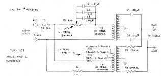
I have Put the Xfourmer out of the SL3s in the Acoustat 121 interface a put the Odyssry type crossoven in on the centape an done some other mades ....like on the sedary side ran the setup like Soundlabe dose with out the 50k res......Just the .1mf caps in the setup an have got great sound an can run the 3ea panel M3 to full output...
Great fun...
So do you see the Crossover setup useing the centap as in the Odyssey as a way to get beter sound an more output... are just a way to make the sound of the same xfourmer an panels sound diff??
I have Put the Xfourmer out of the SL3s in the Acoustat 121 interface a put the Odyssry type crossoven in on the centape an done some other mades ....like on the sedary side ran the setup like Soundlabe dose with out the 50k res......Just the .1mf caps in the setup an have got great sound an can run the 3ea panel M3 to full output...
Great fun...
Attachments
Last edited:
The ML CLX high frequency panel torrid has 4 input taps so I'll guess it's the same transformer as the rest as the ML reserve series. (And they just choose the tap to suit the different models and just have 1 part to inventory /buy in better volume).
The CLX LF EI core has no taps. Later this spring a friends CLX will get upgraded next and we'll take pictures of each board, the magnetics, and trace the crossover schematic for the curious out there.
They did use high speed/soft recovery diodes in the HV step up supplies ( 2 supplies one for Hf and LF with what seems to be different number of steps in each so different operating voltage?).
Another friend has a ML Electromotions - the step up is a tiny EI not much larger than a wall wart.
The crossover is electrolytics in the LF section and polyesters in the HF section.
The Dayton Wright XG8/10 used a 39 pound EI core 80,000 ohm secondary made by Hammond, although it was crossed over to a tweeter (Piezo at first , ribbon later) at about 3k. It used just a small air core choke in series with the transformer to roll off the HF output of the cells. It also used a series 4 ohm power resistor in series with the input (bypassed with a 750 uf motor start cap) to provide some series impedance for early solid state amps fragile output stages- which Nelson Pass / Joe Sammut bypassed for clients with beefier Threshold amps)
Last edited:
Yes Post all an any info on ML an any others ESL... The Look of the size of the.torrid in the summit look just like the Antek transformers
i know that it not........i gess i well have to go with some torrids...or i well never know?? if there sound is better or just diff.......................................
thanks for your time also..
i know that it not........i gess i well have to go with some torrids...or i well never know?? if there sound is better or just diff.......................................
thanks for your time also..
So do you see the Crossover setup useing the centap as in the Odyssey as a way to get beter sound an more output... are just a way to make the sound of the same xfourmer an panels sound diff??
The Odyssey crossover is basically a tweak of the SL3 crossover arrangement shown in Figure (B) from post#46.
A lot of added complexity for what may be a small audible improvement.
Driving the center-tap with a series RLC network fills in the dip in the response just above crossover providing a more linear equalization of the dipole roll off in the 300Hz - 600Hz range. There is quite a bit of interaction between the CT drive and the main drive signals, so a lot of modeling and measuring went in to optimizing the parts values.
Attachment shows simulated response with and without the center tap drive connected.
Blue = with CT drive
Attachments
what do the transformers in esl's do?
can someone please explain to me me what these torroids do? do these convert 6 volt to 2700 volts? or how many volt do you need to go to the stators? Also how many volts do you need to go to the diaphram? is the thing that plugs into the wall just a transformer also? and if so what is its input and output..
Thanks for you time...
The Odyssey crossover is basically a tweak of the SL3 crossover arrangement shown in Figure (B) from post#46.
A lot of added complexity for what may be a small audible improvement.
Well as with any ESLs....even small changes can make a diff.......the Zobel set up on the input res..... it a 1ohm 20watt....cap can be from 5mfs to 10mf.....5mf was the winner in my case.......this is best place to start for anyone with these type res input setups...
That one cap can set the sound of the ESLs output...i have put all new caps in ever place in these crossovers.....but i went back to all stock caps an changed that one cap an got the topend i was looking for.....go figg.
thanks
Well as with any ESLs....even small changes can make a diff.......the Zobel set up on the input res..... it a 1ohm 20watt....cap can be from 5mfs to 10mf.....5mf was the winner in my case
Agreed, sometimes small changes can make all the difference.
In my experience though, small changes in the 200Hz - 500Hz range aren't nearly as critical as at 1kHz - 4kHz. That was what I was trying to get at.
The 1ohm-10uF network your mentioned(red box on schematic) is a shelving network for the top octave.
Attachment #2 shows response trends for CX1 values of 10uF, 5uF, 2uF.
Another network you might consider adjusting to your preference is the midrange contouring network CX3-LX1-(RX7-RX10). You can modify the depth of the adjustment by changing the 3ohm resistance(green box on schematic). Attachment #3 shows response trends for resistance values of 2ohm, 3ohm, 5ohm. I think you will find this adjustment quite critical in balancing the range (smooth-detailed-harsh) of the midrange sound. The apparent depth of image is usually also affected.
Attachments
How Cool is what you know about all ESL,???.........
thanks bolserst...
I have pulled the Crossover out on the ceter tap of the ML....Prodigy
i dont have a schematic for the Prodigy.....or i would post it so you could give input...
Mr Powers sent it to me right before he left...but my pc died with it..
But it sounds better i think?? ....The Biger panel 16X48... has more output for sure with the coil in the ct....but you know how it is it well take time to go back an forth....the pro..setup on the ct its vary close to the re-qust i posted...same size panels..
I put in the 2.5 mh.18ga...What happens if i put in a 12ga coil in???..No res... on the Prodigy ct...the res.....adds a sound i dont like?? should i add the Zobel type setup to that spot...
.just the coil sounds good if you get things setup right....I pulled the coil up... it was swed down flat...i have it standing now it sounds much better...
One thing is for sure.... all the caps an res. an coils in Any Crossover ...Care need to be taken on were an how there monted...just gluing all these parts down can Kill about 1/2 your sound if not more...like for the bass driver i have put some pading under the coil an got low & better bass...an i find that the caps have better top end an give More output if the pull up in the air.
..an not glued down at all...
Anyone can try this an see what i mean..if not right in there setup can allways go back..
....
Hell ML with a pr of Ascents has even put the cap in one speaker in one drecshion an in the other..the other way...it took me some time find this...an to get that pr of speaker to sound right....
Gees so ck you ML an all speakers for this...what ever way you go..keep the caps the same in the pr....
Had a guy thats trying sale Me aNother pr of Prodigy come over...I set my pr up with Re-worket panels an blue his mind...he cant even play his now...he think there at lest 5-6db more output out of my panels.......there a lot life in the older logans thats being tossed right the trash-can.... But that life.... thanks
The CLX LF EI core has no taps. Later this spring a friends CLX will get upgraded next and we'll take pictures of each board, the magnetics, and trace the crossover schematic for the curious out there.
Gooday ticknpop , I am wondering whether you made any headway on that particular project ?
For may part , I would be most interested in any further information that you may have at your disposal , as the ML factory warranty clock is rapidly running down on my CLX's , leaving me free to make broken speakers out of working ones
") .
.If all along you had a nagging suspicion that there is no geometrically feasible way to wind a toroidal coil efficiently, raise your hand.
Good for you for recognizing a geometry koan... and for being honest.
But here is the industrial solution anyway (about halfway through the video). Judging from the toroid transformer videos, they must all be wound in India.
Manufacturer Of High Quality Toroidal Transformers - YouTube
Kind of like snapping a carabiner on an eye-bolt, a 12-inch ring with a hinged door is put on the 3-inch toroid core.
The ring is spun around (while the core sits still) and as it spins it is loaded from an external wire spool with the exact length of wire needed.
Then the ring is spun again, but this time, unloading the wire in turns on to the core (which is slowly rotated to space the turns).
Ben
Last edited:
just for fun
I remembered that i had some small toroid transformers. I though they where 220V / 15V but it turned out that they are 6V
I measured 1:71 at 1000Hz (2 transformers)
They are with nomex insolation but no other information (manufacture, Watts). The saturation >200Hz is a bit more then 20Vrms.
Here the measurements i made:
An externally hosted image should be here but it was not working when we last tested it.
An externally hosted image should be here but it was not working when we last tested it.
Nice to see data like that. Thanks.
No clear to me what "loaded" primary, etc. means? Can you describe the test jig better.
With 10-ohms minimum input impedance, no big issue having a few ohms in series with the input wiring in order to present a nicer load to the amp. Of course, using two toroids with parallel inputs, that makes the load worse for the amp.
At 1:71, may not be necessary to have two toroids per channel (with the downsides of needing to wire primaries in parallel and secondaries in series).
Ben
I remembered that i had some small toroid transformers. I though they where 220V / 15V but it turned out that they are 6V
I measured 1:71 at 1000Hz (2 transformers)
They are with nomex insolation but no other information (manufacture, Watts). The saturation >200Hz is a bit more then 20Vrms.
Here the measurements i made:
Based on response and saturation measurements they look to be perfectly useable for a hybrid ESL.

Looking at your impedance measurements, there seems to be a considerable shift in resonance frequency between curves for 300pF and 460pF load. Is it possible that the 460pF measurements were taken with two transformers but the 300pF was taken with a single transformer?
Based on response and saturation measurements they look to be perfectly useable for a hybrid ESL.
Looking at your impedance measurements, there seems to be a considerable shift in resonance frequency between curves for 300pF and 460pF load. Is it possible that the 460pF measurements were taken with two transformers but the 300pF was taken with a single transformer?
No.
Yes, for a hybride they are very nice indeed. Only problem is: I not like hybride esl so it was just for the fun to measure the transformers.
Last edited:
- Status
- This old topic is closed. If you want to reopen this topic, contact a moderator using the "Report Post" button.
- Home
- Loudspeakers
- Planars & Exotics
- Toroids for ESL's