Thanks for the encouragement and direction, everyone.
Jer, if I put the 120 vac terminals between the transformer input and output, I'll be good?
I definitely will test for arcs before final assembly. Do I need to incorporate the HV supply to test, or only what you suggested by putting the stators together and supply amplified signal to the transformers?
I now understand why folks go for the VHB tape method - fixturing and applying the epoxy is tedious! First half of one panel is curing now.
Bruce
Set the stators up just as if it was completed with some plastic spacers in between them and run them with the bias and the amp with a source just like normal.
It would be safer to have the inputs more separated although having the 120v in the middle will add some protection.
But, If it arcs over to the 120v line you can First blow the bias transformer and/or it can travel up the line and take something else out.
Just like Lightening can do !!
My computer will sometimes reset from arcs off of my Variable HV supply to just the ground side as it travels up the ground side and interrupts the either the CPU or power supply.
Up the ground side of the line (Green wire) !!!
It hasn't done it lately but it has in the past though.
I just completed this test with my new stators and it passed.
Although I didn't use the transformers because my supply puts out 13.61Kv.
jer")
It would be safer to have the inputs more separated although having the 120v in the middle will add some protection.
But, If it arcs over to the 120v line you can First blow the bias transformer and/or it can travel up the line and take something else out.
Just like Lightening can do !!
My computer will sometimes reset from arcs off of my Variable HV supply to just the ground side as it travels up the ground side and interrupts the either the CPU or power supply.
Up the ground side of the line (Green wire) !!!
It hasn't done it lately but it has in the past though.
I just completed this test with my new stators and it passed.
Although I didn't use the transformers because my supply puts out 13.61Kv.
jer
Attachments
Update - panel resonance frequency?
I got my panels arc tested with 30 volts on the transformer inputs, at various frequencies. I sure learned the value of the 10 watt current limiting resistor. I must have momentarily left the input frequency at an extreme and that resistor started smoking! At first I thought it was transformer. Luckily my amp and transformer are fine. Kind of fun to hear them quietly sing with no diaphragms!
I got one of my panels with Mylar applied, 6 um, 1.5% stretch, though I had an accident while taking it off the flat gluing surface and tore one of the four 5" x 11.5" cells. I took the opportunity to hold the panel near one of my main speakers at different frequencies. It resonates at approximately 135 +/- 10 Hz. Is this too high? Do I need to stretch it less? I think I will be crossing over at around 300 Hz. Maybe up to 500. Need some help soon, as I'd like to keep going. I am using epoxy - great shear strength, but it pulls up pretty easily. Thanks, Bruce.
Hi,
What is the slope? An active 24db/oct. filter at twice the resonance or so should be adequate. However if you use some light damping(even a light covering material does some job) requirements could be relieved.
High tension also can result in residual resonances up to higher frequencies.
So if the design allows(sufficient d/s spacing for width) it's desirable to have less tension. For this reason some people use heat shrinking. This has it's own caveats as you may end with not sufficient tension and diaphragm collapsing into the stator.
Read this whole thread , IMO it's valuable:
http://www.diyaudio.com/forums/planars-exotics/168069-esls-have-bad-decay-plots.html
The epoxy is good for the purpose but it's important the surfaces are very clean(wiped with alcohol or acetone). It usually tends to increase bonding to mylar over the months. Another nice property of epoxy is it's usually possible to scratch it off the plastic spacers via knife.
How did you manage to rip the mylar off? If a stretching frame is used then it's quite easy to put it over the panel and cut mylar with a hot soldering iron after curing. Difficult to do wrong. Also the mylar is pressed into by weight of the frame and bonding surface becomes extremely flat. Some vegetables could be used for higher downwards force but it's not really necessary
.Regards,
Lukas.
Attachments
Last edited:
Thanks for the link to thread on decay plots Lukas - good stuff. I have a DCX2496 crossover, so I will use at least a 24 dB slope.
I tore the Mylar when lifting the panel off the stretching table, where I had not cut completely through the Mylar. It was easy enough to get the old epoxy off the frames. I have been using alcohol - probably just need to give it more cure time. Thanks for the great tip on using a soldering iron!
I tore the Mylar when lifting the panel off the stretching table, where I had not cut completely through the Mylar. It was easy enough to get the old epoxy off the frames. I have been using alcohol - probably just need to give it more cure time. Thanks for the great tip on using a soldering iron!
I have been messing with transformers lately again.
With the 100watt version I can get as low as 330Hz to 370Hz with a 40Vrms input just before the onset of core saturation and distortion starts to rise considerably.
The 50watt version should have similar performance as they are designed with the same frequency and voltage parameters in mind.
This should give you an idea of how low you can go with your crossover vs how big your amplifier is.
If you are using a amplifier only capable of 28Vrms (100watts) you may be able to get down to but no lower than 233Hz or else you have core saturation and sever distortions below this frequency.
jer
P.S. Lukas, Your stretcher setup looks very nice !!! 
With the 100watt version I can get as low as 330Hz to 370Hz with a 40Vrms input just before the onset of core saturation and distortion starts to rise considerably.
The 50watt version should have similar performance as they are designed with the same frequency and voltage parameters in mind.
This should give you an idea of how low you can go with your crossover vs how big your amplifier is.
If you are using a amplifier only capable of 28Vrms (100watts) you may be able to get down to but no lower than 233Hz or else you have core saturation and sever distortions below this frequency.
jer
P.S. Lukas, Your stretcher setup looks very nice !!!
Last edited:
P.S. Lukas, Your stretcher setup looks very nice !!!
Hi,
Thanks, but this frame has had some flaws.So I have redesigned the stretcher to be significantly larger and pull all four sides with wing nuts.
Making the stretcher wider and longer has one advantage : highly stretched areas at corners which could form partial resonances are just cut off.
I have been able to achieve about 2-3% Fs accuracy through mechanical stretching now; however there are some steps , like gluing mylar with glue and not double sided tape which lets it go over 12 hour period through which epoxy cures. Also it's very important to stretch the film lightly but evenly prior to gluing to the frame.
Concerning core saturation : LR crossover cross at -6db output. This means at crossover point the trafo is already receiving only half of the input voltage - assuming no clipping. If heavy clipping occurs at either amplifier or DSP then even DC can be fed into the transformer.
So a cutoff frequency could be lowered somewhat. Furthermore, most of peaks in music material occur below about 200-220Hz. So core saturation is much less likely above this frequency unless excessive active EQ boost is used.
Regards,
Lukas.
Panels Completed!
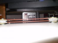
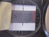
Well, I finally got these panels put together several weeks ago and thought I'd update with a few pics. I ended up with 1.25% stretch. With the setup shown, I was able to measure fairly accurately to 1/64". The stretched Mylar is so fragile, that it broke once when I nicked it lightly with my magnifier!
Well, I finally got these panels put together several weeks ago and thought I'd update with a few pics. I ended up with 1.25% stretch. With the setup shown, I was able to measure fairly accurately to 1/64". The stretched Mylar is so fragile, that it broke once when I nicked it lightly with my magnifier!
Attachments
Panels Completed!
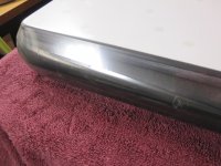
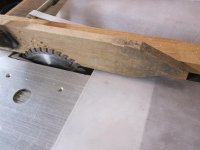
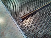
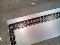
I used 1/16" Lexan for spacer material. It is 3/4" wide, leaving 1/8" beyond the edges of the stator to block high voltage. I ripped it into strips on my table saw, deburred and sanded it. After aligning the glued front and back stator holes, I notched the Lexan, as a gauge point for re-alignment on the final glue-up. Also 3/8" wide aluminum extrusions were epoxied over the internal Lexan spacers.
I used 1/16" Lexan for spacer material. It is 3/4" wide, leaving 1/8" beyond the edges of the stator to block high voltage. I ripped it into strips on my table saw, deburred and sanded it. After aligning the glued front and back stator holes, I notched the Lexan, as a gauge point for re-alignment on the final glue-up. Also 3/8" wide aluminum extrusions were epoxied over the internal Lexan spacers.
Attachments
Panels Completed!
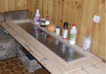
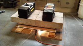
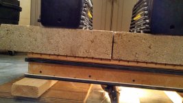
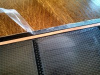
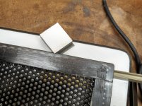
Whether gluing the Lexan to the stators, stators to the Mylar or stiffeners to the stators, I used the shown weighted setup. Sanders really emphasizes flatness of the assembly and enough pressure to get everything together with a consistent caliper. Nothing special about the grooved plywood - something from another project. Murphy struck once before I realized the drainage slope on my garage floor, so the assembly slid on the epoxy and smeared it. It was cold in the garage, which was good for increasing open time on the epoxy. The trouble light added some warmth for curing the epoxy.
Whether gluing the Lexan to the stators, stators to the Mylar or stiffeners to the stators, I used the shown weighted setup. Sanders really emphasizes flatness of the assembly and enough pressure to get everything together with a consistent caliper. Nothing special about the grooved plywood - something from another project. Murphy struck once before I realized the drainage slope on my garage floor, so the assembly slid on the epoxy and smeared it. It was cold in the garage, which was good for increasing open time on the epoxy. The trouble light added some warmth for curing the epoxy.
Attachments
Panels Completed!
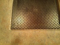
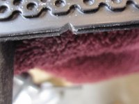
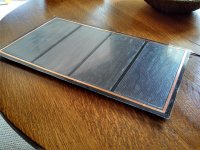
I cut strips of "Press and Seal" food wrap to mask off the Mylar before spraying on the Lycron Crystal. It has low tack, but don't leave it on too long. I'm pretty sure I applied too much Lycron in one coat, as it dried streaky. Too much experience, I guess, at getting a full wet out coat when spraying paint. The copper charge ring was applied with the conductive adhesive to the Lycron side of the Mylar. I told my wife the panels looked like place mats, while curing on our dining room table!
I cut strips of "Press and Seal" food wrap to mask off the Mylar before spraying on the Lycron Crystal. It has low tack, but don't leave it on too long. I'm pretty sure I applied too much Lycron in one coat, as it dried streaky. Too much experience, I guess, at getting a full wet out coat when spraying paint. The copper charge ring was applied with the conductive adhesive to the Lycron side of the Mylar. I told my wife the panels looked like place mats, while curing on our dining room table!
Attachments
Very Cool!!!
There may be some tricks to spraying the licron to get it more clear but I haven't sprayed enough of it to tell you what they are.
I typically spray it and swab it around to save on the product and that works good too.
Once you get them sandwiched together you may not even notice the translucency against the black stators.
jer
I cut strips of "Press and Seal" food wrap to mask off the Mylar before spraying on the Lycron Crystal. It has low tack, but don't leave it on too long. I'm pretty sure I applied too much Lycron in one coat, as it dried streaky. Too much experience, I guess, at getting a full wet out coat when spraying paint. The copper charge ring was applied with the conductive adhesive to the Lycron side of the Mylar. I told my wife the panels looked like place mats, while curing on our dining room table!
Hi,
You can clean off the Licron with a cotton wipe soaked in acetone and re-apply.
Regards,
Lukas.
Hi,
You can clean off the Licron with a cotton wipe soaked in acetone and re-apply.
Regards,
Lukas.
I found that the coating tends to be cloudy where wet streaks occur in the application, and especially so when applied in humid conditions. However, the streaking would not adversely affect performance, only the cosmetics. It's hard to apply a uniform coating from an aerosol can.
Panels Completed!
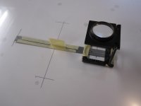
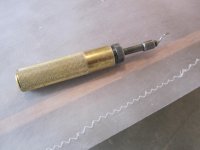
Thanks for the feedback guys. I wonder if wiping the Lycron on with a microfiber cloth would put down an even coat? The pic below shows the corner block that was positioned in the Lexan notches - two on one side, one on the other. This kept everything aligned while the epoxy cured.
I was so pleased that both panels worked as soon as I fed them! I was almost expecting them to not work, for some reason or another.
A few initial observations:
I'm surprised and pleased at how loud they can play, given their size and only driving with 30 wpc, crossed at 500 Hz.
I really agree with Charlie's friend, who summed it up by calling them "remote headphones"! I thought I knew what beaming was with the 12" full rangers that I have, but these really do. Charlie - you are so right about how phenomenal a female voice sounds! I just hear so much more - in everything I listen to.
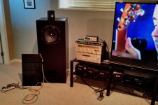
I have not even made frames for them yet. The internal stiffeners and using epoxy makes them quite rigid. The pic shows them on the floor, but I elevated them and did some A/B'ing with a make-shift open baffle mid-bass and am convinced I will need to go that route, as the ported bass takes away the cleanness of the stats.
All in all, very happy with them and it was such a rewarding project. I just unexpectedly acquired a pair of BG 50's and have been playing with them. The stats are great for one listener and I believe I prefer them for that, but the wide dispersion of the BG's is very appealing. I have some questions about them I will ask in a new post.
Thanks again for the direction and support on this build!
Bruce
Thanks for the feedback guys. I wonder if wiping the Lycron on with a microfiber cloth would put down an even coat? The pic below shows the corner block that was positioned in the Lexan notches - two on one side, one on the other. This kept everything aligned while the epoxy cured.
I was so pleased that both panels worked as soon as I fed them! I was almost expecting them to not work, for some reason or another.
A few initial observations:
I'm surprised and pleased at how loud they can play, given their size and only driving with 30 wpc, crossed at 500 Hz.
I really agree with Charlie's friend, who summed it up by calling them "remote headphones"! I thought I knew what beaming was with the 12" full rangers that I have, but these really do. Charlie - you are so right about how phenomenal a female voice sounds! I just hear so much more - in everything I listen to.
I have not even made frames for them yet. The internal stiffeners and using epoxy makes them quite rigid. The pic shows them on the floor, but I elevated them and did some A/B'ing with a make-shift open baffle mid-bass and am convinced I will need to go that route, as the ported bass takes away the cleanness of the stats.
All in all, very happy with them and it was such a rewarding project. I just unexpectedly acquired a pair of BG 50's and have been playing with them. The stats are great for one listener and I believe I prefer them for that, but the wide dispersion of the BG's is very appealing. I have some questions about them I will ask in a new post.
Thanks again for the direction and support on this build!
Bruce
Attachments
It is so refreshing to see another successful DIY ESL build!!
Congratulations !!!!
Can you tell us your final overall dimension's especially the length between the inner spacers.
You may find that they may be a little less directional if you have your sections running vertical instead of horizontal.
In other words rotate them 90 degrees and see how they sound then.
jer
Last edited:
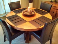
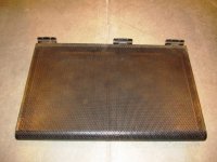
Thanks Jer! Each area of available diaphragm is 11.5 x 5", four per panel. Overall stator size, including the spacer between them is 12.75 x 22.5". From the pic, you can see what determined the size - surplus store shelving!
I have had the understanding that the overall width of the panel controls the dispersion angle, not the width of the sections in the panel. I can see that the panel turned 90 degrees would give me a wider sweet spot, but would the dispersion angle be wider because the narrower panel sections? I would try it right now, but they are not set up because I'm playing those BG R50's....some Little Feat, Waiting for Columbus!
I have had the understanding that the overall width of the panel controls the dispersion angle, not the width of the sections in the panel. I can see that the panel turned 90 degrees would give me a wider sweet spot, but would the dispersion angle be wider because the narrower panel sections? I would try it right now, but they are not set up because I'm playing those BG R50's....some Little Feat, Waiting for Columbus!
Attachments
Last edited:
- Status
- This old topic is closed. If you want to reopen this topic, contact a moderator using the "Report Post" button.
- Home
- Loudspeakers
- Planars & Exotics
- My 1st ELS build - first question!