My 1st ESL build - first question!
Greetings! This is my first ESL project, though I have been planning (obsessing) about it for a long time and have been reading this forum for quite a while. I am amazed at the knowledge and generosity of those on this site. Thanks in advance for your help!
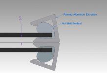
I initially was going to do a 3M tape build, but have been thinking about doing something else, to minimize the stator area that doesn't move the diaphragm. I have some extruded aluminum channel that will give me 1.72 mm d/s spacing. Also the panel would be quite rigid and may not need any other framework. Please see the attached drawing. Will this even work, with the aluminum between the stators?
Greetings! This is my first ESL project, though I have been planning (obsessing) about it for a long time and have been reading this forum for quite a while. I am amazed at the knowledge and generosity of those on this site. Thanks in advance for your help!
I initially was going to do a 3M tape build, but have been thinking about doing something else, to minimize the stator area that doesn't move the diaphragm. I have some extruded aluminum channel that will give me 1.72 mm d/s spacing. Also the panel would be quite rigid and may not need any other framework. Please see the attached drawing. Will this even work, with the aluminum between the stators?
Attachments
Last edited:
Hi,
From my (hard) experience it's better to avoid metal parts so close to stators. Leakage problems are much more pronounced and safety might be compromised as well. From your drawing I don't understand how do you plan to isolate aluminum from the stators and mylar charging ring?
While some people have found that certain types of double sided tape do work, from my experience its not reliable in most cases under higher tension. Tapes tend to creep. Then mylar loses tension and wrinkles develop at the edges which produce unwanted noises.
My material of choice for spacers is some kind of plastic(plexi, PVC or so). PVC is a nice material in that it is not brittle but the downside is high dielectric constant(about 4), so it will increase capacitance of the panels quite much.
The best glue I have found to bond is slow-curing epoxy. It equalizes itself so surface is very flat. Full bonding strength to mylar develops after a longer time only. Epoxy has an additional advantage that it does not bond really well to most plastic spacer materials so it's not so difficult to rip it off with a knife and replace mylar if needed.
For sure, others might have found completely different methods to work the best.
Regards,
Lukas.
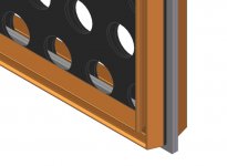
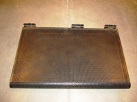
Thanks Jer and Lukas for your input. I definitely will abort that idea. What I am about is building something myself using creativity (from others and myself) to get great results at a low cost. So I like to use materials and tools I have or are low cost to get. The problem with that is sometimes the material doesn't really fit the purpose, which might be the case with this aluminum extrusion. I have another idea that I want to run past you. The aluminum is 6063-T6 - very rigid and painted with a durable finish. Charlie and others have said that the stators can tend to vibrate. While it may not noticeably effect the sound, it seems that it would waste energy and contribute to d/s slapping. So that is why I am trying to make a rigid panel. I would use the same extrusion to brace the panel over the internal spacers. See the pics and please let me know what you think.
Attachments

Stators and Coating
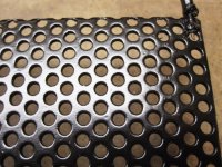
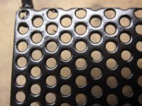
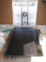
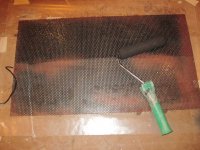
I am going to post a little more info on where I am so far. I bought a bunch of perforated steel shelving, so that determines the size of my panels 12.75"x 22" (324 x 559 mm). I'll start with 2 and build 2 or 4 more later. The metal is 20 gauge, 3 mm holes, 40% open area. They already had 5 mils power coating thickness on them. I sanded them pretty well and put on 3 coats of clear polyurethane with a foam roller, sanding in between coats. With rolling, I could force the coating into the holes. See the video of my contraption to keep the poly from running while drying. Panel turner - YouTube . I would try this approach again, but use a short nap roller instead of foam, as it tends to leave bubbles, that need to be sanded out. I have also sprayed a couple coats of black enamel on them. So far I have about 10 mils total coating thickness on each side - is that enough?
Note: on my previous post the 3 mm stator holes are shown way over-size. The extrusion is about 10 mm wide.
Attachments
Last edited:
Hi,
Your idea to dry paint is rather interesting.
However I would like to warn you that painting the sheets so that they can reliably withstand ~7-10 kV at home is very very difficult. So there is a high possibility of arching, leakage etc. Perhaps using higher resistance mylar coating could help to some extent.
Another problem is that panels of this size will be very directional.
IMO flat panels are much more reliable and easier to build in the end at home if made from PVC insulated wires instead of perforated sheets.
Advantages of wire panels :
1) Almost impossible to arc
2) Allows for electrical segmentation
3) Frames usually supply rigidity; no need to add additional reinforcement to prevent vibration.
4) Lower total capacitance, especially if electrical segmentation is used
5) IMO easier to build compared to properly coated perforated sheets
Regards,
Lukas.

Hello again. Taking a cue from vrusso123, who also is just starting a project, to formally introduce myself. My name is Bruce. I live in northwest Iowa and work as an engineering tech at a window manufacturer. My interest in hifi audio started with a part time job at an audio store, while going to tech school for electronics repair. This was over 30 years ago. We were selling the RTR line and they had the ESR-6 stat that could be used as an add-on to their column speakers. The owner of the store had the RTR DR1’s (360 degree stat), which was an awesome speaker. That was my only exposure to ESL’s. Pursuit of this hobby was mostly on hold while raising a family, but I now have more time for it and in the last couple years I built some large enclosures for the Audio Nirvana 12 full range drivers. The bass and midrange is clean but the high end distortion is bothersome. After deciding to build some ESL’s, I acquired the Behringer 2496 crossover and bi-amped the 12’s with my Hsu Research Ventriloquist’s – that alone confirmed how much better things will sound with the ESL’s. Mostly though, I’m going off of the enthusiasm of folks on this forum! My budget is limited, so I will start with cabinets I have. Other equipment I have is a vintage Onkyo 7090 (110 wpc), Marantz receiver (30 wpc ) and an Onkyo 606 AV receiver. Expecting to need some more power for the stats, before I’m satisfied.
Just finished going through the dielectric coating thread, which has convinced me that I should add a few more coats to the stators. Thought I would try the clear insulating varnish – hoping that it will not attack the last coats of black enamel. Thanks, Bruce.
Just finished going through the dielectric coating thread, which has convinced me that I should add a few more coats to the stators. Thought I would try the clear insulating varnish – hoping that it will not attack the last coats of black enamel. Thanks, Bruce.
Welcome to the Forum Bruce!!!
If you already have a base coat of enamel you can use some clear acrylic enamel in a spray can.
I have found that this stuff works very well.
Or some automotive type clear coat if you are using your own sprayer.
In my area I have found some Sherwin Williams brand for about $60 a gallon, with the reducer I think.
It was the cheapest that I could find in bulk and has a very high dielectric strength.
I have not tried it yet but it should work fine as well.
Some are using polyurethane with great results but I am not sure if it will bond with enamel as it might lift the base coat or bubble it.
I have had this happen to me one my earlier panels with enamel on top of polyurethane.
If you get the thicker 2x or 3x Rustoleum stuff it is very cost effective.
I have found that it is good for at least 900 volts to 1200 volts per mil or so if not more.
In some of my tests I have gotten has high as 1700 to 1900 volts per mil before breakdown had occurred.
jer")
If you already have a base coat of enamel you can use some clear acrylic enamel in a spray can.
I have found that this stuff works very well.
Or some automotive type clear coat if you are using your own sprayer.
In my area I have found some Sherwin Williams brand for about $60 a gallon, with the reducer I think.
It was the cheapest that I could find in bulk and has a very high dielectric strength.
I have not tried it yet but it should work fine as well.
Some are using polyurethane with great results but I am not sure if it will bond with enamel as it might lift the base coat or bubble it.
I have had this happen to me one my earlier panels with enamel on top of polyurethane.
If you get the thicker 2x or 3x Rustoleum stuff it is very cost effective.
I have found that it is good for at least 900 volts to 1200 volts per mil or so if not more.
In some of my tests I have gotten has high as 1700 to 1900 volts per mil before breakdown had occurred.
jer
Last edited:
Thank you, Jer!
I actually have some Rust-oleum clear gloss, so I think I'll put a few coats of that on. Now that I've got about 10 mils on each side, do you think it's necessary to any further build up the non-diaphragm side of the stators?
I read in one thread how you were contemplating building a powder coat oven. Have you considered a barbeque grill? My stators will fit in my Weber, so I may try it for curing spray paint - as my wife hates the stink when I've put them in the kitchen oven.
I actually have some Rust-oleum clear gloss, so I think I'll put a few coats of that on. Now that I've got about 10 mils on each side, do you think it's necessary to any further build up the non-diaphragm side of the stators?
I read in one thread how you were contemplating building a powder coat oven. Have you considered a barbeque grill? My stators will fit in my Weber, so I may try it for curing spray paint - as my wife hates the stink when I've put them in the kitchen oven
.
Last edited:
Usually about 10 mils is good.
You can set them up in a mock configuration without the diaphragms with the bias supply and transformers and run a signal into them to make sure that they don't arc.
I have seen many skip this test only to have to tear them apart again and add more coating to the stators.
I did finally get some powder coating material to try out,But I haven't had the time to mess with it yet.
I need to make me a fluidizing bed to coat the screens with next.
My next panels I will be using the paint method on some TIG wire stators.
I also just made a quick sample of some screen sprayed with polyurethane as well.
This came out good as it was just a test and the coating is not thick enough yet to be used as a ESL but I will use this method possibly to finish my ES headphones.
jer
Pneumatic Stretcher
I am really trying to get these panels up and running by Christmas. I have the power supplies and transformers put together, thanks to Jazzman's plans. I am now working on the pneumatic stretcher. The perimeter of my rectangular board is about 76", which calculates to a 24" tube. Should I go with a 20"? What should the approximate width and depth of the trough be that the tube lays in? Also has anyone used Gorilla Glue polyurethane adhesive to attach the mylar to the frame? I would use the recommended 3M Scotch Grip, but I'm not too comfortable with an instant bond. Thanks! Bruce.
I am really trying to get these panels up and running by Christmas. I have the power supplies and transformers put together, thanks to Jazzman's plans. I am now working on the pneumatic stretcher. The perimeter of my rectangular board is about 76", which calculates to a 24" tube. Should I go with a 20"? What should the approximate width and depth of the trough be that the tube lays in? Also has anyone used Gorilla Glue polyurethane adhesive to attach the mylar to the frame? I would use the recommended 3M Scotch Grip, but I'm not too comfortable with an instant bond. Thanks! Bruce.
Gorilla glue won't work with mylar and it foam's up and this would cause an irregular surface and might cause wrinkles.
Plus it needs to be exposed to the air in order to cure.
I use epoxy to bond the mylar to its frames.
Use a slow setting type as this will allow you to get it on your frames all you need is a very very thin coat.
I have never had any bonding issues yet with epoxy, although you can peel it off with a razor blade should you need to replace the Diaphragm and/or start over.
You can also scuff the frames up a bit with some fine 220 to 320 grit sandpaper if you like as this helps too.
It holds well enough that I have snapped a frame from over tensioning the diaphragm with a heat gun while it was unmounted, once, as a test.
After I lay the frame down on to the mylar I sandwich it with a piece of glass and weight it down.
It is best to just drop it in place so be accurate as if you try to move the frame you will risk wrinkling the mylar and make a mess of the epoxy causing you to have to start over with a fresh piece.
Keep a sample of the epoxy you had used and as it starts to harden this is the time to carefully take the top piece of glass off.
This is because some of the epoxy will ooze out and can get stuck to the glass.
One time I wait too long and nearly lost the frame but I got it unstuck by carefully using a long craving knife and a razor blade to pry it off of the glass.
Of all of the times I have done this I think I only screwed one up and had to start over because I smeard the epoxy all over the diaphragm.
This was because I was mounting two within the 12.5" width and missed my spot laying it down and one other one that had moved causing a wrinkle.
The wrinkled one was still worked and functioned fine but it irritated me so I replaced it anyhow.
Once you lay it down and if you feel that there is to much epoxy oozing out on the inside of the frame you can carefully scoop it up around the perimeter with a toothpick and wipe the excess off on a paper towel.
Thus one of the main reasons to use a slow setting type.
I used a 1 or 2 hour type at first and once I got it down I started using a 30 minute type.
Then weight it down.
Weighting it down is basically optional but it will assure you a super flat piece in the end as this is something that you will have perfect for your method of construction.
Even if you use the DSTape method the process is basically the same.
You just drop it on to the mylar and push it down so that it sticks all of the way around the perimeter.
Sorry I don't have any pictures of this process but I will in a few days from my newest build that is almost complete here,
A Segmented Stator Desktop ESL
The trough for the tube need only be deep enough to keep the tube from slipping out or shifting and if a 20" will stretch that far it might work but then again that is stretching it a bit (he,he,he).
You might be better off getting a 24" tube.
Cheers !!
jer
I am really trying to get these panels up and running by Christmas. I have the power supplies and transformers put together, thanks to Jazzman's plans. I am now working on the pneumatic stretcher. The perimeter of my rectangular board is about 76", which calculates to a 24" tube. Should I go with a 20"? What should the approximate width and depth of the trough be that the tube lays in? Also has anyone used Gorilla Glue polyurethane adhesive to attach the mylar to the frame? I would use the recommended 3M Scotch Grip, but I'm not too comfortable with an instant bond. Thanks! Bruce.
You can also use various contact glues. Its easier to work with. Some will work when applied to one side ; others need to be applied on both.
The key to success is to use a very thin layer of glue and wait until the surface is dry. Then the film must be pressed hard into the spacer by using fingers. Some experimentation is needed. Many polyurethane based contact adhesives can be diluted with Acetone to a ratio ~3:1(acetone:glue) or so depending on initial viscosity, then applied with a brush to one or both sides.
Regards,
Lukas.
Last edited:
... I am now working on the pneumatic stretcher. The perimeter of my rectangular board is about 76", which calculates to a 24" tube. Should I go with a 20"? What should the approximate width and depth of the trough be that the tube lays in?
Hi Bruce,
I suspect either size tube should work-- the larger tube would be fine if it fits tight enough to not hang loosely, and the smaller tube would certainly stretch to fit. The stretcher jig should have rounded corners/edges which are sanded smooth, and the height of the jig sides needs to be greater than the width of the tube. Rubbing some baby powder over the top edges of the jig will allow the film to slide easy without snagging and tearing-- but if you use baby powder be sure to clean any powder residue off the diaphragm with an alcohol wipe before applying the conductive coating. The jig doesn't need a trough for the tube unless you just want one-- the tube just sits on the side edges of the jig. You want all air sucked out of the tube initially so that it lays flat and you want the tube positioned near the top edge of the jig so it pulls the film over the jig edge at a shallow (not sharp) angle.
BTW, were you able to find the toroidal transformers? The last time I checked, the Antek AN506's were sold out.
Good luck with your project!
Charlie (jazzman)
Thanks for the advice guys. I'm going to go with the epoxy on both the polycarbonate spacers and the mylar. Got 9 oz, 30 minute stuff at Hobby Lobby for $11. I've done some tests on the 1/16" Lexan and epoxy. It doesn't hold real great but should do the job. At least I'll be able to get them apart if needed.
Charlie, I got my Antek transformers around a year ago. Glad I got them - if those units were not available and work as good as it sounds they will, the higher dollar transformers may have dissuaded from me not to even starting the project!
Almost have the stretcher completed. I understand the recommended stretch on 6 um film is 1.5% ?
Thanks,
Bruce
Attachments
You can add a custom primary to any toroid power transformer.
That is how I run mine, added a 10 turn winding to give me 1:67 per core.
I explain how in this thread,
http://www.diyaudio.com/forums/planars-exotics/161485-step-up-transformer-design-2.html#post2101604
http://www.diyaudio.com/forums/planars-exotics/161485-step-up-transformer-design-2.html#post2103369
Good deal that you already have them!!
Yes. the epoxy will peel off easily but it is strong enough to hold mylar to the frame with much lateral tension.
Have you tested the integrity of the stator coating yet?
Now that you have the bias supply and the transformers ready?
Sorry I can't stress this enough I have seen nearly every new build fail on the first fire up and have to be torn apart just to make it thicker and destroy a perfectly good piece of mylar!!
http://www.diyaudio.com/forums/plan...1st-els-build-first-question.html#post3219035
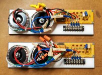
Great job on your interface units!!!
Except I would keep the input Primay wires very much away from the secondary side and bias supply!!!
That barrier strip is not enough to keep 5kv to 10 kv and more isolated enough from jumping over and possibly damaging your amplifier.
Even if your bias supply is only 2kv to 3kv the peaks coming out of the transformers will be much much higher especially if your amp can produce a large voltage swing !!!
Cheers !!
jer
That is how I run mine, added a 10 turn winding to give me 1:67 per core.
I explain how in this thread,
http://www.diyaudio.com/forums/planars-exotics/161485-step-up-transformer-design-2.html#post2101604
http://www.diyaudio.com/forums/planars-exotics/161485-step-up-transformer-design-2.html#post2103369
Good deal that you already have them!!
Yes. the epoxy will peel off easily but it is strong enough to hold mylar to the frame with much lateral tension.
Have you tested the integrity of the stator coating yet?
Now that you have the bias supply and the transformers ready?
Sorry I can't stress this enough I have seen nearly every new build fail on the first fire up and have to be torn apart just to make it thicker and destroy a perfectly good piece of mylar!!
http://www.diyaudio.com/forums/plan...1st-els-build-first-question.html#post3219035
Great job on your interface units!!!
Except I would keep the input Primay wires very much away from the secondary side and bias supply!!!
That barrier strip is not enough to keep 5kv to 10 kv and more isolated enough from jumping over and possibly damaging your amplifier.
Even if your bias supply is only 2kv to 3kv the peaks coming out of the transformers will be much much higher especially if your amp can produce a large voltage swing !!!
Cheers !!
jer
Last edited:
I had added to the previous post, But, I had went over the 30 minute time limit for editing.
I do get about 1:134 transformation using one core with a ten turn primary, But I use 4 cores right now for the following reasons.
#1 I'm using smaller panels so I need to double my transformation ratio in order to match the efficiency of the woofer that I am using.
#2Using multiple cores also lowers my lowest frequency point of core saturation.
#3 The two 120v windings are bifillar wound and this greatly increases the transformers self capacitance not to mention all of the extra winding's that I have yet to remove.
Even though my cores do measure better than the Antek's as posted by Bolserst, I do have issues with my cheapy amp with even just two of them.
This is mainly due to the very high 1:268 (1:256 as measured) transformation ratio that it takes to achieve my goal of good low frequency response while maintaining a high level of efficiency.
This keeps the impedance range and saturation limits well within the capability's of my Aiwa CX-NA707 without it shutting down.
My bigger amps are monsters and don't have such issues and thus the cause of my last panels burning up !!! He,he,he,he
I like to at least get down to about 240hz to 300hz at full power without any saturation of the cores.
I just wanted to clarify my statement of 1:67 ratio per core.
I am currently finishing up my new panel and then I will be working on a transformer recipe that DIYers can use and build for much cheaper than what is currently available and still achieve a higher level of performance than using the current methods.
I believe this is very possible and I have done quite a few preliminary calculations as I have been through the very same struggle as every one else has.
In fact it was the main reason it took me from 2004 to 2010 to actually get back into it......The Transformer Issue.
More on that later and keep up the great work!!
jer
Last edited:
Almost have the stretcher completed. I understand the recommended stretch on 6 um film is 1.5% ?
Thanks,
Bruce
Opinions differ on how much tension is best. I can tell you that I stretched my 6um diaphragms to 1.5% elongation and it works well for me. I would not go with less than 1% or much above 1.5%.
Nice work on that interface!
- Status
- This old topic is closed. If you want to reopen this topic, contact a moderator using the "Report Post" button.
- Home
- Loudspeakers
- Planars & Exotics
- My 1st ELS build - first question!