When the 1.5 volt battery test are performed you can use your ears...
The "sound" when the battery are connected should be equal to the "sound" when you disconnect, and also the "sound" (this is difficult to describe..) itself should be "clean" (a pulse that start and stop without ringing..).
With my own AMTs I can get a similar "sound" when I connect a coil in parallel and thus changing the "properties"..
Then the physical movement of the diaphragm are more similar and the "sound" similar and best described as "ringing" - like when you tap on a tight drum skin and not like when you tap on a solid surface.
Both my AMTs and dynamic 8" drivers are made for DC operation and the 1.5 volt battery moves the diaphragm / cone and it stays there till the 1.5 volt are removed - then the diaphragm / cone moves back to "neutral" - changing the polarity - then the diaphragm / cone moves in the opposite direction and stays there till the 1.5 volt are removed..
This behavior you will not find in ordinary designed AMTs or dynamic drivers.
What happen there are that the 1.5 volt will try to move the diaphragm / cone (to the intended position the DC voltage was supposed to cause), but mechanical and electrical properties of the design will cause the diaphragm / cone to be repositioned back to closer to the neutral position (creating a spike / pulse with possible ringing at start and stop of the movement). When the 1.5 volt voltage are removed the diaphragm / cone will not just return to the neutral position, but the "forces" that have caused the misalignment will create ringing as the diaphragm / cone are forced to cross back over the neutral position etc. etc..
The properties / "forces" that destroys the DC performance are part of what limits the LF response.
I have observed that most AMT designs are created with basis in the Heil patent and are thus mostly limited in LF to between 1kHz and 2kHz with both SPL and THD under control. By tweaking the Heil design I have not really seen any AMT that can manage to have both SPL level and THD under control below 1kHz. There are designs that can go lower than 1kHz, and I have tested what they are good for in reality.
As Mark & Daniel made AMTs based on the Heil patent that was good sized and should run well below 1kHz I bought a pile of them and made a OB / line source baffle where I connected them in series / parallel with first 8 units pr. side and then 16 units pr. side. As 500 or 700Hz (if I remember correctly) was the LF response of one unit - then the increased surface area should extend the usable LF response at least down to around 200 - 300Hz in theory.. But that was in theory as in practical use I ended up with 2kHz (using -6dB/oct filter) as the lowest usable LF extension.. Trying to play as full range without filter was a complete disaster due to the diaphragm was shorting "all over the place"..
I ripped a couple of them open and the folding style and resulting very low xmax would cause shorts between the folds and thus prevent any real low frequency use. There was other properties that also would limit the low frequency response.
As I never have made any copy of the Heil patent I do not really know the limitations and possibilities of that design...
Last edited:
Thanks for your elaborate reply, RayCtech.
Again you put it in words what I only have a hunch about.
DC characteristics is a good indicator for the LF response and/or max excursion.
One shouldn´t need to put together a whole diaphragm to evaluate different solutions.
It should also be possible to make a simple "magnetometer" comprised of a probe coil that is moved at a constant speed through the field.
Connect to a voltmeter or a VU-meter and you can do some relative measurement. Like how sparse the rods shall be or if the field is un-even.
So what does a non Heil AMT look like then? Anything you would like to share?
So what does a non Heil AMT look like then? Anything you would like to share?
The exterior looks are quite similar due to the used slot loading principle and the basic electro magnetic engine principle, but every single property of the design are a factor of 2 to 10 different - so a 1:10 / 10:1 or maybe closer to 100:1 / 1:100 overall design difference are a reality.
To extend the LF response alone 10 to 20 times (from 1 - 2kHz to 100Hz) cannot be achieved without some radical changes. I will soon power up the first bass AMTs where the goal was to reach 20Hz with full SPL. From the design view they should work as intended, but who knows - there may be some practical limitations I have not foreseen that comes into play and become a "show stopper". The bass AMT design was finished a long time ago and the 100 diaphragms that was made then have never been folded or tested. It is not due to I expect the bass AMT to be a failure I have not finished them, but due to I already have both a pure AMT setup that plays full range, and also a hybrid setup with my 8" taking care of the lowest frequency octaves, and it is simply more fun to design something new and totally different then to do time consuming assembly works.
I used to glue the diaphragm with melt glue:
![URL]](/community/proxy.php?image=http%3A%2F%2F%5BURL%3Dhttp%3A%2F%2Fimg89.imageshack.us%2Fi%2Famt28leder002.jpg%2F%5D%5BIMGDEAD%5Dhttp%3A%2F%2Fimg89.imageshack.us%2Fimg89%2F2126%2Famt28leder002.jpg%5B%2FIMGDEAD%5D%5B%2FURL%5D&hash=6be56c9643a968a3f36c7abf6b47d397)
![URL]](/community/proxy.php?image=http%3A%2F%2F%5BURL%3Dhttp%3A%2F%2Fimg203.imageshack.us%2Fi%2Famt28leder004.jpg%2F%5D%5BIMGDEAD%5Dhttp%3A%2F%2Fimg203.imageshack.us%2Fimg203%2F7783%2Famt28leder004.jpg%5B%2FIMGDEAD%5D%5B%2FURL%5D&hash=ce25aee3a7662a4ea0fae90247c900fe)
I have mounted a small tube and pressed it to 0 shape.
In my newest diaphragms the pleats only have a with of 1mm. ,and I want to glue it in the folding tool.
I have tried several types of glue,but the problem is either it is too thin or too heavy.
Silicone is ok,but needs to be pressed to get all in.
Now i use this:
![URL]](/community/proxy.php?image=http%3A%2F%2F%5BURL%3Dhttp%3A%2F%2Fimg842.imageshack.us%2Fi%2Flimning001.jpg%2F%5D%5BIMGDEAD%5Dhttp%3A%2F%2Fimg842.imageshack.us%2Fimg842%2F9641%2Flimning001.jpg%5B%2FIMGDEAD%5D%5B%2FURL%5D&hash=a90f31edcd35a8138b25af96c61a0e01)
![URL]](/community/proxy.php?image=http%3A%2F%2F%5BURL%3Dhttp%3A%2F%2Fimg819.imageshack.us%2Fi%2Flimning002.jpg%2F%5D%5BIMGDEAD%5Dhttp%3A%2F%2Fimg819.imageshack.us%2Fimg819%2F4827%2Flimning002.jpg%5B%2FIMGDEAD%5D%5B%2FURL%5D&hash=4b04aa2fb7ef8a62b99f76f43bd412d8)
I have grindet the needle and pressed it.It is the largest 1.2mm. and a small pump 2ml.
Bernt
I have mounted a small tube and pressed it to 0 shape.
In my newest diaphragms the pleats only have a with of 1mm. ,and I want to glue it in the folding tool.
I have tried several types of glue,but the problem is either it is too thin or too heavy.
Silicone is ok,but needs to be pressed to get all in.
Now i use this:
I have grindet the needle and pressed it.It is the largest 1.2mm. and a small pump 2ml.
Bernt
Last edited:
![URL]](/community/proxy.php?image=http%3A%2F%2F%5BURL%3Dhttp%3A%2F%2Fimg820.imageshack.us%2Fi%2Flarge001m.jpg%2F%5D%5BIMGDEAD%5Dhttp%3A%2F%2Fimg820.imageshack.us%2Fimg820%2F9296%2Flarge001m.jpg%5B%2FIMGDEAD%5D%5B%2FURL%5D&hash=9e5eb8e3272fe5ffa6cb5fe400e0707b)
![URL]](/community/proxy.php?image=http%3A%2F%2F%5BURL%3Dhttp%3A%2F%2Fimg90.imageshack.us%2Fi%2Famt85001.jpg%2F%5D%5BIMGDEAD%5Dhttp%3A%2F%2Fimg90.imageshack.us%2Fimg90%2F9591%2Famt85001.jpg%5B%2FIMGDEAD%5D%5B%2FURL%5D&hash=9b6173ca317e978a482c7c24f96dbbc4)
![URL]](/community/proxy.php?image=http%3A%2F%2F%5BURL%3Dhttp%3A%2F%2Fimg15.imageshack.us%2Fi%2Famt85002.jpg%2F%5D%5BIMGDEAD%5Dhttp%3A%2F%2Fimg15.imageshack.us%2Fimg15%2F3657%2Famt85002.jpg%5B%2FIMGDEAD%5D%5B%2FURL%5D&hash=3fe226bca18437b7ba89f0645c8e1fa3)
It seems you are allright,although you are a bit jealouse.Pardon my English.
I like to share all my ideas,some are not a ceeper,but I think I am close to what is possibly to make with this size of diaphragm.
The change in my last,or maybe latest diaphragm is 30 stripes or leads,in a 40x170x6,5mm frame.I will show how the frame is build later.And the folding tool too.
Bernt
I like to share all my ideas,some are not a ceeper,but I think I am close to what is possibly to make with this size of diaphragm.
The change in my last,or maybe latest diaphragm is 30 stripes or leads,in a 40x170x6,5mm frame.I will show how the frame is build later.And the folding tool too.
Bernt
![URL]](/community/proxy.php?image=http%3A%2F%2F%5BURL%3Dhttp%3A%2F%2Fimg849.imageshack.us%2Fi%2F1002uc.jpg%2F%5D%5BIMGDEAD%5Dhttp%3A%2F%2Fimg849.imageshack.us%2Fimg849%2F6083%2F1002uc.jpg%5B%2FIMGDEAD%5D%5B%2FURL%5D&hash=bab27d3a00c8b6240d9f8d33d74887bd)
![URL]](/community/proxy.php?image=http%3A%2F%2F%5BURL%3Dhttp%3A%2F%2Fimg405.imageshack.us%2Fi%2F30leder40x170x65mm1m85m.jpg%2F%5D%5BIMGDEAD%5Dhttp%3A%2F%2Fimg405.imageshack.us%2Fimg405%2F5659%2F30leder40x170x65mm1m85m.jpg%5B%2FIMGDEAD%5D%5B%2FURL%5D&hash=73b6b0ff7e641f108d29b233050aaf80)
Black is THD red 2`Harmonic.
Now I have to make one more.It sounds good too.
Impressive
")
You should figure out why the distortion increases above 4kHz before you relax and stop building and only listen.
In real life the distortion are not decreasing above 9kHz like your measurement indicates.
The displayed measurement of THD will decreasing with frequency due to the way it is calculated.
With my AMTs this decreasing amount of THD shows up as the THD are falling with frequency even if the THD in real life are steady.
Your measurement indicate - THD are 30dB down at 9kHz - but I expect THD are much higher than your measurement - specially above 9kHz...
If you figure out what causes the distortion then you can relax.
The distortion can even be caused by the amplifier you use....
Last edited:
![URL]](/community/proxy.php?image=http%3A%2F%2F%5BURL%3Dhttp%3A%2F%2Fimg109.imageshack.us%2Fi%2F30leder40x170x65mm1m85m.jpg%2F%5D%5BIMGDEAD%5Dhttp%3A%2F%2Fimg109.imageshack.us%2Fimg109%2F5659%2F30leder40x170x65mm1m85m.jpg%5B%2FIMGDEAD%5D%5B%2FURL%5D&hash=fe71cfcfe82b34ed1926b0779195c013)
I use this measurement to calm me down:
Its the same conditions,measured with Holm Impulse.
Still, I will try another amp,and a dome tweeter for testing.
Bernt
Yes there THD decreases from 2.5kHz...
Due to the harmonics are removed step by step due to the mathematics....
So truth is => a even level of THD will show up as decreasing level above 2.5kHz... If THD shows up as a even level or increases with frequency then there are trouble..
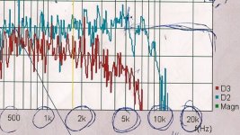
Attached a picture showing (wrongly low distortion) THD (2nd and 3rd) of my AMT.. I understood that this was not possible, but in reality the THD was slowly decreasing up to above 20kHz.
Attachments
Last edited:
![URL]](/community/proxy.php?image=http%3A%2F%2F%5BURL%3Dhttp%3A%2F%2Fimg11.imageshack.us%2Fi%2Faurasound1m28vrew.jpg%2F%5D%5BIMGHTTPDEAD%5Dhttp%3A%2F%2Fimg11.imageshack.us%2Fimg11%2F8213%2Faurasound1m28vrew.jpg%5B%2FIMGHTTPDEAD%5D%5B%2FURL%5D&hash=9f1fdbb0a667b239786db8d97f2d6165)
You are right RayCtech,there are some distortíon over 5Khz.It is not the measurements tool.I have tried to change amp to a classD too.No difference,just a bit more 2`Harminic.
Bernt
Looks like +20dB 2nd and +30dB 3rd harmonic before the measurement limitations fades out (down) at 9kHz.
The fact that both 2nd and 3rd harmonic are behaving identical in the measurement above 9kHz are strange as the 3rd harmonic should have decreased in level due to the measurement bandwidth limitation - at a lower frequency than the 2nd harmonic.
The 18kHz peak in the SPL measurement may indicates some kind of breakup / oscillation...
And may be the cause for the rising distortion....?
I have observed breakup / oscillation / resonance in diaphragms, in the metal / magnet assembly, in the "folding" cassette.
The breakup / oscillation / resonance in the metal / magnet assembly have I observed in branded AMTs, and then the metal / magnet assembly will emit a high frequency sound if you hit / tap it with something hard.. I have measured the emitted SPL level up to 60dB in branded AMTs that are caused by this breakup / oscillation / resonance in the metal / magnet assembly....
![URL]](/community/proxy.php?image=http%3A%2F%2F%5BURL%3Dhttp%3A%2F%2Fimg14.imageshack.us%2Fi%2F30leder40x170x65mm1m85m.jpg%2F%5D%5BIMGDEAD%5Dhttp%3A%2F%2Fimg14.imageshack.us%2Fimg14%2F5659%2F30leder40x170x65mm1m85m.jpg%5B%2FIMGDEAD%5D%5B%2FURL%5D&hash=1eb688f7f79b89e0f1c5aa8ce4918377)
![URL]](/community/proxy.php?image=http%3A%2F%2F%5BURL%3Dhttp%3A%2F%2Fimg22.imageshack.us%2Fi%2Famt850012.jpg%2F%5D%5BIMGDEAD%5Dhttp%3A%2F%2Fimg22.imageshack.us%2Fimg22%2F4745%2Famt850012.jpg%5B%2FIMGDEAD%5D%5B%2FURL%5D&hash=4c27c53d6815f47109d6bc47f766d0d9)
- Status
- This old topic is closed. If you want to reopen this topic, contact a moderator using the "Report Post" button.
- Home
- Loudspeakers
- Planars & Exotics
- Diy AMT