Just came across this video of the ADAM Audio factory visit. They show some nice construction details of their AMT tweeters. The fixture they use for actually folding the pleats is pretty neat: Adam Audio factory visit - YouTube
Just came across this video of the ADAM Audio factory visit. They show some nice construction details of their AMT tweeters. The fixture they use for actually folding the pleats is pretty neat: Adam Audio factory visit - YouTube
This is fantastic video, thank you very much! Especially that jig for folding AMT diaphragm...
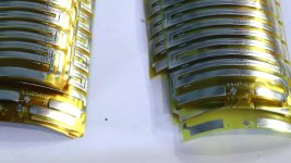
Yes great get with that video. Just what we need. It looks to me that the conductive trace is only on one side of the diaphragm for Adam too. Would you agree? In their white paper they mention that the trace is attached via heat. Perhaps one can just iron on the trace to mylar?
I will look around the house for something resembling the jig. What I had in mind, at first, was to use IDE connectors to weave. The pins are precisely spaced and about the right size. I'll get some paper clips from work today to try it.
I want to try folding first and etching second, if I can pull it off.
I also want to try a much larger surround compared to the active area. Perhaps making the active area 50 mm high only (1 row of tape) but using 2 more pieces for the surround. I will horn load so the driver can be larger than the active area.
I'm not so sure, have a look here where she is folding the diaphragm. I saved the video to file for intel. In principle having the diaphragm on only one side should increase even order HD because of the asymmetry, but I wonder whether it matters.
I may try alternating the sides. Then short circuits are unlikely.
I may try alternating the sides. Then short circuits are unlikely.
An externally hosted image should be here but it was not working when we last tested it.
Etchant For Aluminum
I have had very good luck using the the solution described here http://www.uic.edu/sph/glakes/harts1/HARTS_library/Semenoff.txt to etch aluminum.
It is is much better controlled and far safer then NaOH. Also, it does not attack most of the common PCB photoresists.
I have had very good luck using the the solution described here http://www.uic.edu/sph/glakes/harts1/HARTS_library/Semenoff.txt to etch aluminum.
It is is much better controlled and far safer then NaOH. Also, it does not attack most of the common PCB photoresists.
Thanks for the alternate etcher. None of my permanent markers have been able to stand up to the NaOH so far.
Yesterday I was fooling around and had 2 ideas worth pursuing.
1/ IDE cables make excellent stencils for drawing/cutting evening spaced, straight traces. The 1 mm pitch of them gives some flexibility too. You can get your serpentine pattern done quickly. and the well indentations stop the ink from running.
2/ Cable ties would make a nice folding jig. Imagine running a rod through the holes so that they sit like keys on a key chain. I will buy some and try to fold the diaphragm up and down them, and then clamp it and see if etching gets in the gaps. The plastic should make a good mask.
What do you think would be better for the trace width with cable ties, 2.5 or 3.6 mm?
What sort of dimensions are people using for the pleats? It looks to me like the pleats have a center to center spacing of somewhere between 1.5 to 2mm. But how deep? Perhaps 4 or 5 mm?
As to the etchant I mention above, you can see an example of one use I made of it here: http://www.diyaudio.com/forums/soli...ont-panel-lettering-4.html#post2454656http://
I have also used it to completely etch through a pattern in aluminum flashing (it was for a meter face). That worked well too, although there was a small amount of undercutting.
![URL]](/community/proxy.php?image=http%3A%2F%2F%5BURL%3Dhttp%3A%2F%2Fimg542.imageshack.us%2Fi%2Famtmembramtegn.jpg%2F%5D%5BIMGHTTPDEAD%5Dhttp%3A%2F%2Fimg542.imageshack.us%2Fimg542%2F491%2Famtmembramtegn.jpg%5B%2FIMGHTTPDEAD%5D%5B%2FURL%5D&hash=f1a49ffd782e5ca51e318af92474dd6c)
Mine are like ESS, 2,5 mm. center to center,and 4,5 mm. depth.
My drawing has spacing 5mm.
Download,incraese,decrease and print.Length 130mm.
I have not tried on alu yet.
Wich one is best? laser or inkjet?
Bernt.
I don't have a laser so I always do photetching and use an inkjet to make the transparency, which works incredibly well, but adds application/exposure/development of photoresist as an extra step. I never had good results with toner transfer- pinholes, poor resolution, etc. But your mileage may vary. It would be very cool if you could make a film/aluminum sandwich and put that directly into your laser printer, but I think that the conductivity of the aluminum would cause some problems with the way those printers work.
Cannon used to have a Gold Foil transfer paper in the 1990's that was used in copiers but they quit making it and I have never seen it since.
I was really neat stuff and I have used it.
It was used to print Seals mainly and to have lettering done in gold.
I have been trying to think of ways to do this but I have not tried anything yet.
You put your paper in sandwiched between these two sheets and run it though your copier (or laser printer as they were still very new at the time) and out comes your paper that has the gold foil transferred to it from the image that was being copied!!
jer")
P.S. Maybe this is what I remember seeing as it was bonding to the toner and not copied from an image.
I only saw it a few times and it was 20 years ago.
http://askville.amazon.com/Home-pri...old-silver/AnswerViewer.do?requestId=15652686
This is the Stuff !!!
http://compare.ebay.com/like/180795311106?var=lv<yp=AllFixedPriceItemTypes&var=sbar
I was really neat stuff and I have used it.
It was used to print Seals mainly and to have lettering done in gold.
I have been trying to think of ways to do this but I have not tried anything yet.
You put your paper in sandwiched between these two sheets and run it though your copier (or laser printer as they were still very new at the time) and out comes your paper that has the gold foil transferred to it from the image that was being copied!!
jer
P.S. Maybe this is what I remember seeing as it was bonding to the toner and not copied from an image.
I only saw it a few times and it was 20 years ago.
http://askville.amazon.com/Home-pri...old-silver/AnswerViewer.do?requestId=15652686
This is the Stuff !!!
http://compare.ebay.com/like/180795311106?var=lv<yp=AllFixedPriceItemTypes&var=sbar
Last edited:
yeah it didnt print in gold, now that would be neat =) with a bit of wire bonding you could make basic transistors.
as for toner transfer, people do indeed get mixed results based on the specific paper used. I use staples photo presentation paper, which is actually inkjet paper, but used in a rather nice colour A3 Xerox colour laser docucolour (it pays to have a design background and a family of designers) but the paper changes from store to store apparently, I grabbed some confirmed good stuff based in info from a thread here, works great.
as for toner transfer, people do indeed get mixed results based on the specific paper used. I use staples photo presentation paper, which is actually inkjet paper, but used in a rather nice colour A3 Xerox colour laser docucolour (it pays to have a design background and a family of designers) but the paper changes from store to store apparently, I grabbed some confirmed good stuff based in info from a thread here, works great.
The stuff I saw was really real gold and is most likely why they had stopped making it.
But, I didn't know that this stuff was available on the hobbiest market even if it is aluminium foil as a heat transfer type.
Yes, I have had issues with different paper's as well so far I have only got HP photo paper to work with my printer.
I had gotten some other type of cheaper brand and it turned out to be to thick for my printer as it Jam's on the little edge that is sticking out from the toner cartridge.
So now the issue would be a bonding material for between the Aluminium foil and diaphragm it self as the transfer method must come first or it will shrink it unless you are using Kapton.
I have some but I think it is 1 mil stuff although it may work.
I haven't made an AMT as I mentioned but it is the same process for a planar driver as well as I am not trying to go OT here.
jer
Last edited:
There is a comment from Nelson Pass that the best sounding ESS AMT's used polyethylene -which also has the virtue of being cheap and widely available.
I know that polyethylene melts pretty well and sticks like glue to a clothes iron if you happen to bring the hot iron near the poly (don't ask how I know this). So I wonder if you couldn't just heat bond the polyethylene to the aluminum foil. No glue needed then.
I know that polyethylene melts pretty well and sticks like glue to a clothes iron if you happen to bring the hot iron near the poly (don't ask how I know this). So I wonder if you couldn't just heat bond the polyethylene to the aluminum foil. No glue needed then.
I think that in ADAM's whitepaper they say that the trace is heat bonded to the substrate on their diaphragm.
AMT's don't seem to require extreme precision with the traces (they are thick compared to orthodynamic headphone drivers). Still I'm curious about a very fine pitched AMT. I guess that the pleat resonance could be manipulated. Don't want any audible resonances in a DIY AMT headphone.
I wonder if, with some photoresist, one could use a magnifying glass to shrink a mask to a desired much smaller size when exposing the diaphragm to UV. I think that is what they do in the PC industry. The mask is much larger than the silicon wafer traces.
- Status
- This old topic is closed. If you want to reopen this topic, contact a moderator using the "Report Post" button.
- Home
- Loudspeakers
- Planars & Exotics
- Diy AMT