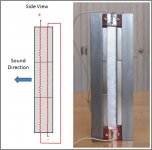
I'm thinking about experimenting with a ribbon tweeter design with multiple ribbon elements physically in parallel. See the attachment for a side view drawing. The squiggly lines are the edge-on view of two ribbons, separated by about .25". The two ribbon will be connected in series electrically so the current flows in the same direction in both ribbons (otherwise they would cancel each other out). The magnets are the three gray blocks with the poles facing out in the drawing.
The photo on the right is a picture from my old "Another DIY Ribbon" thread of what it would look like from the front. I'm going to use the same basic design but will beef up the magnets (they will now be .5 X .5 X 2" N42, three on each side) and the steel frame (to avoid saturation and maximize gap strength). The ribbons are each .5" wide and 6" long aluminum. I'm not sure how/if it will work, but that's at least half the fun of DIY. If it doesn't work I'll fall back to a single ribbon.
Has anyone seen this done before?
My thought is that with double the ribbons carrying the same current in the magnetic field, I could get increased efficiency (i.e. more SPL for a given input power). The ribbon in the back has to "play through" the ribbon in the front but a very thin ribbon element in front shouldn't provide significant attenuation or filtering of the rear element - at least that's the theory. There is no reason I would have to stop at two stacked ribbons. I could see going to 4 or six ribbons so long as the magnets are wide enough.
Anyone want to guess what will happen?
Attachments
Hi
Wasn't this done in one of the early Apogee ribbons? -for mid or HF?
I don't know if it would add efficiency ..., sort of an isobaric ribbon..??
george
The similarity to isobaric woofers did cross my mind but I'm not sure if you get the same coupling effect at tweeter frequencies or if they would act like two independent closely space tweeters.
Hi
Wasn't this done in one of the early Apogee ribbons? -for mid or HF?
I don't know if it would add efficiency ..., sort of an isobaric ribbon..??
george
The Full Range uses 2 tw but as a bipole, the scintilla has 2 and 2 tw also as a bipole.
The effect is not efficiency, since every ribbon gets only the half voltage, but bipole have a different behavior with beaming and affect basically the soundstage.
george a - the photos I found looks like the Apogee ribbons had a ribbon that was comprised of six individual narrow conductors adhered to a single non conducting backing. These six stripes where then wired in series. I think this was probably done to increase the ribbon resistance to make it easier for an amplifier to drive. My idea is different in that it is multiple ribbons stacked in parallel.
Groove-T - You are right that the power is divided between the two ribbons but if my configuration increases the effective area of the driver as a whole, the increased area will also increase efficiency.
I've got all the pieces, now all I have to do is find the time to build it and take some measurements.
Nice ribbon...i have Apogee stages...an yes the 6runs are to get the ribbon up to about 3-4ohms.... an have been thing about ..ribbon death...did you make your ribbon in the pic...looks great...keep Diying...thanks for any an all info...goodluck
I did make that ribbon as a prototype of a bigger ribbon array I described in an old thread:
http://www.diyaudio.com/forums/planars-exotics/50162-another-diy-ribbon-thread.html
FYI: I've got a website that boils it down to fewer pages:
DIY Ribbon Project
The prototype is long gone but the big ribbons are still running strong in my home theater.
ribbon stacking is no good idea because one gap "loads" the other
in a single gap the energy is symmetrical distributed
in a double gap the energy rises towards the inner edge
so the field gets stronger across the gap ca 20% and the ribbon will twist on larger excursions (with all kinds of other negative effects)
sorry for the bad news ..
in a single gap the energy is symmetrical distributed
in a double gap the energy rises towards the inner edge
so the field gets stronger across the gap ca 20% and the ribbon will twist on larger excursions (with all kinds of other negative effects)
sorry for the bad news ..
ribbon stacking is no good idea because one gap "loads" the other
in a single gap the energy is symmetrical distributed
in a double gap the energy rises towards the inner edge
so the field gets stronger across the gap ca 20% and the ribbon will twist on larger excursions (with all kinds of other negative effects)
sorry for the bad news ..
Are you saying that the two ribbons would couple acoustically or are you saying that the second ribbon would somehow distort the magnetic field in the gap, making the magnetic field less linear?
In either case, I'll probably still give it a try since it shouldn't take very long to set it up with two ribbons in the gap.
Thanks,
Denis
it is a magnetic issue but of course there is also an interaction thru the air so each ribbon is not symmetrically loaded across the width
but I think it is a minor issue (though it will add and cause the same consequences)
btw 2 ribbons side by side have a strong combfilter effect ....
see mundorf PDFs - a deep wide null at 30deg and 16kHz
this is anything else but not high fidelity
good luck
but I think it is a minor issue (though it will add and cause the same consequences)
btw 2 ribbons side by side have a strong combfilter effect ....
see mundorf PDFs - a deep wide null at 30deg and 16kHz
this is anything else but not high fidelity
good luck
I did it months ago.up to 4 layers connected in parallel. i used 0.8 microns al foil.My computer with all measurements is broken. I will post the measurements when repaired. I used a 8 ohms resistors in series with the ribbons. The sensitivity is the same up to 10 Khz.It decreases after. Multayer sounded bett
Bruno
Bruno
I did it months ago.up to 4 layers connected in parallel. i used 0.8 microns al foil.My computer with all measurements is broken. I will post the measurements when repaired. I used a 8 ohms resistors in series with the ribbons. The sensitivity is the same up to 10 Khz.It decreases after. Multayer sounded bett
Bruno
Very interesting. I look forward to seeing your measurements. Do you have any photographs of the ribbon? How did you measure the relative sensitivity and make sure the same power was getting to the ribbon? Running with multiple ribbon elements will change the impedance which will change the power getting to the ribbons. Where you able to measure the current and voltage at the ribbon and calculate the power?
Denis
Sorry to have taken so long to respond to your question. I completely rebuilt my PC. I wanted to redo the measurements before posting. You will find them in post #20 in this thread: http://www.diyaudio.com/forums/planars-exotics/195044-stackable-ribbon-module-2.html .
Bruno
- Status
- This old topic is closed. If you want to reopen this topic, contact a moderator using the "Report Post" button.
- Home
- Loudspeakers
- Planars & Exotics
- Stacked Ribbon?