Usually dome mid-ranges do not utilize a spider. I would guess because the voice coil and dome are one piece, the dome's surround acts on part of the spider. Anyone correct me if i am wrong.I would have thought that a spider is mandatory for this driver, no?
How else will it not rock and become un-centered in the gap, and rub??
Sorry i thought you meant the Dayton. Well the plan is to dismantle the Dayton. This would require taking out both the dome/surround and the voice-coil. I will install a new coil and glue my carbon fiber lamellas to the coil. I think i know what you are thinking, but i believe the support rods are there to essentially suspend the sphere in the gap. The lamella group/coil isn’t dropped into the gap. Also mbl uses ferro-fluid in the gap and if used correctly can be used to center the voice-coil.not the stock dome midrange unit, the MBL unit, it requires a spider, or are you going to just glue to the dome or dome edge??
Last edited:
Yes the dayton - but the MBL clone is a different matter.
I do not think that the support rods will play any role in placing the VC in the gap keeping it parallel and centered, unless the construction is very precise.
I'd personally prefer to use a spider to maintain the centering.
If you can manage to produce a melon that is very stable and symmetrical, then perhaps a VC only construction will work, but I find that to be really problematic, and very difficult to do.
Also why use the dayton? I'd want the max flux in the gap, which would require a lot more magnet and motor... although for just proof of concept that doesn't matter.
_-_-bear
Right this is merely a proof of concept as well as testing different variables,as discussed previously. What i meant to say was that the rods suspend the group in the gap and also might help with centering. I believe the whole assembled unit has to be pretty precise. Also I believe mbl uses the centering force of the ferro-fluid to further help. Producing a "melon that is very stable and symmetrical" is part of the reason, to practice for the real thing.Yes the dayton - but the MBL clone is a different matter.
I do not think that the support rods will play any role in placing the VC in the gap keeping it parallel and centered, unless the construction is very precise.
I'd personally prefer to use a spider to maintain the centering.
If you can manage to produce a melon that is very stable and symmetrical, then perhaps a VC only construction will work, but I find that to be really problematic, and very difficult to do.
Also why use the dayton? I'd want the max flux in the gap, which would require a lot more magnet and motor... although for just proof of concept that doesn't matter.
_-_-bear
Last edited:
I will definitely experiment with one.make ur life easy, use a spider?
think about how to keep the walls of the VC parallel to the inner pole piece?
very little is needed to move the vc out of parallel or out of center...
_-_-bear
Because of the total weight of the petals and the low frequency filter I don,t see how it will work without a spider.
Those domes aren,t made to function at 80hz or 100hz with any kind of serious travel probably needed to "flex" these big petals. Ferrofluid isn't going to keep it from rubbing at a low frequency
I don,t know what frequency MBL uses but looking at the dual port bandpass design, it can,t be very high.
Do you know what frequency MBL uses and the order? 2nd ,3rd ? for its midrange?
What do think is the reason MBL did not use carbon fiber for this specific driver? Could it be a combination of poor sensitivity and the need for cooling the aluminum petals would provide because of it? It would seem carbon fiber would be a natural here... And yet they didn,t go that direction.. Just speculation on my part.
Maybe a disimilar material connection will be a bad idea resulting in a smoked coil?
Your low frequency and slope will be extremely important if the petals are not capable of disipating any kind of heat.
I think you have it all wrong. I am not trying to experiment with the "Melon". The big aluminum group. I am using the Dayton for the upper-mid range. This mid-range group operates at 600hz to 3.5khz. All the specifications can be found on post #1.Because of the total weight of the petals and the low frequency filter I don,t see how it will work without a spider.
Those domes aren,t made to function at 80hz or 100hz with any kind of serious travel probably needed to "flex" these big petals. Ferrofluid isn't going to keep it from rubbing at a low frequency
I don,t know what frequency MBL uses but looking at the dual port bandpass design, it can,t be very high.
Do you know what frequency MBL uses and the order? 2nd ,3rd ? for its midrange?
What do think is the reason MBL did not use carbon fiber for this specific driver? Could it be a combination of poor sensitivity and the need for cooling the aluminum petals would provide because of it? It would seem carbon fiber would be a natural here... And yet they didn,t go that direction.. Just speculation on my part.
Maybe a disimilar material connection will be a bad idea resulting in a smoked coil?
Your low frequency and slope will be extremely important if the petals are not capable of disipating any kind of heat.
specifications:
Crossover frequencies: 105Hz, 600Hz, 3.5kHz (Linkwitz-Riley, fourth-order). Acoustic center: 45" (1140mm) from floor. Frequency range: 24Hz–40kHz. Sensitivity: 81dB/2.83V/m. Nominal impedance: 4 ohms. Power handling: 320–500W continuous, 2.2kW peak
I would have thought that a spider is mandatory for this driver, no?
How else will it not rock and become un-centered in the gap, and rub??
The DC gold drivers are designed to rub, teflon on teflon is like ice on ice.
I don't say it's the best since sliced bread, but very practical for a DIYer who needs a motor for experiments with exotic diaphragms. Polymer baskets are good for slaughtering, too.
If one stays away from the lower midrange one could also use the lower excursion and power handling DML exciters. And for the lower midrange, meanwhile I wonder whether the big melon has any other justification of existence than looking funky. One could build a coloumn speaker like RAAL does,
http://www.raal-requisite.com/pages/eternity.html
just with six fiver-coloumns, each wired in a bessel-array. Should give a point source in the disired frequency range, too, with perfectly proven driver technology.
In the sixer-array with gap one could pack the tweeter in the middle.
A Paul Kemble web page - speaker bessel arrays.
A Paul Kemble web page - speaker bessel arrays.
The MBL has so many variables involved with the design that it literally makes my head spin just thinking about it. And all of those of variables need to be in perfect balance for the design to succeed. All of them.. It's not a loudspeaker as much as it's a literal work of art that just happens to play music accurately. A totally insane design when you think about it..
Last edited:
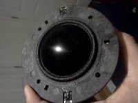
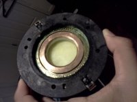
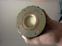
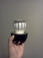
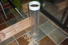
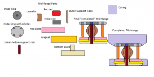
I took the mbl mid apart as shown here. The left over assembly left me a nice little motor from which to work with. I built a little replica merely for fun while the actual parts arrive.
Attachments
Next steps
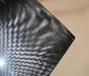
The next steps that will be coming in the next week are. Making a mold out of carbon fiber using a 110mm pipe that will give me the bending radius of 55mm, And cutting the parts labeled: inner-ring, outer-ring, and outer-support-rods.
The next steps that will be coming in the next week are. Making a mold out of carbon fiber using a 110mm pipe that will give me the bending radius of 55mm, And cutting the parts labeled: inner-ring, outer-ring, and outer-support-rods.
Attachments
- Status
- This old topic is closed. If you want to reopen this topic, contact a moderator using the "Report Post" button.
- Home
- Loudspeakers
- Planars & Exotics
- Summer Project - Replication of MBL loudspeaker 101mkII