I have a good 2 months out of school and i decided to build a replication of the loudspeakers MBL 101 mkII. The monetary resources to build a clone at least parts of it are taken care of . The following are the complete information of construction regarding the MBL 101 mkII. This project is inspired by this thread http://www.diyaudio.com/forums/planars-exotics/153337-my-mbl-101e-replicas.html
CLASSIFIED
CLASSIFIED
Additional Driver Info
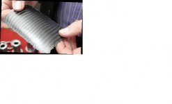
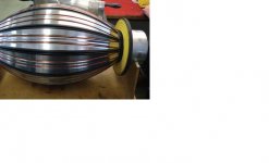
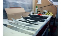
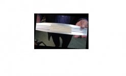
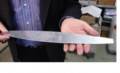
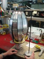
The aluminum lamellas are a sandwich construction of two aluminum wedges held with epoxy resin Wrong. The petals are given 2 days to cool like airplane parts. layers of polyurethane foam are slapped on the back of each lamella to provide damping and additional mass. Each lamella is fitted with 2 thick reddish copper ''wires''. The wires are fitted into the vertical recesses of the petal. The wires add mass and an aesthetic beauty. The recesses of the driver are rolled and not stamped. The whole assembly rest on a cast aluminum plinth coated in automotive grade atracite metallic paint.
The sub woofer
[FONT=Verdana, Arial, Helvetica, sans-serif][SIZE=-1]The woofer is a 12" driver with a 4" voice coil. The voice coil is composed of black anodized aluminum that has a very low thermal resistance, approximately 1 K/W. This gives the system large power handling capability. The voice coil wire is also constructed of high temperature material able to withstand temperatures of up to 360¡C. The wire is glued with the same glue used in the fabrication of motorcycle brakes, and is able to withstand a temperature of 260¡C. As a result, it is almost impossible to destroy the speaker. The air gap is 10 mm high and the moving coil has a winding width of 24 mm. Thus, the speaker possesses an extremely high linear throw, with a maximum of 14-mm peak to peak. The maximum mechanical throw is two times greater -- 28 mm maximum peak to peak.[/SIZE][/FONT]
The cabinet :
Material - MDF
Material thickness - 30mm (1.25")
Port Holes - 2 inches in Diameter
Additional cabinet info
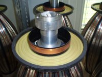
the cabinet has rectangular cross configuration to both stabilize the walls and hold the magnet with polyurethane supports.
specifications:
Crossover frequencies: 105Hz, 600Hz, 3.5kHz (Linkwitz-Riley, fourth-order). Acoustic center: 45" (1140mm) from floor. Frequency range: 24Hz–40kHz. Sensitivity: 81dB/2.83V/m. Nominal impedance: 4 ohms. Power handling: 320–500W continuous, 2.2kW peak.
Right now i am hopping to simply replicate the mid-range and used them as my stereo setup and as research and design along with resources progress the replication of the other 2 drivers will begin. I am learning to use Femm so that i can design and build the magnetic circuit for the mid range.The processes for building the mid range will hopefully be done in parts such as
Step 1 : Magnetic circuit fully designed and optimized in femm
Step 2 : ferrofluid properties such as viscosity,heat tolerance,and Gauss rating can then be calculated
Step 3 : Carbon fiber baking methods can be R&D
Please tell me your thoughts on such a project
Step 1 : Magnetic circuit fully designed and optimized in femm
Step 2 : ferrofluid properties such as viscosity,heat tolerance,and Gauss rating can then be calculated
Step 3 : Carbon fiber baking methods can be R&D
Please tell me your thoughts on such a project
Last edited:
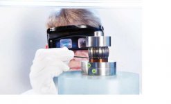
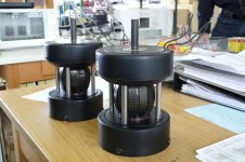
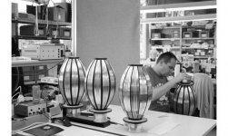
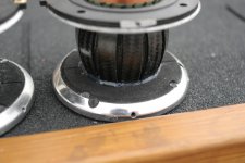
The mid-range
Pictures of the mid-range driver naked
Pictures of the mid-range driver naked
Attachments
-
 mbl-116F-Elegance-f557x334-ffffff-C-309f4ea2-51568967.jpg21.8 KB · Views: 266
 -
 mbl bare naked mid and tweet.jpg12.7 KB · Views: 191
 -
 Mbl mid - computer cut lamnella.jpg13.1 KB · Views: 194
 -
 Mbl mid Baked sheet of carbon fiber.jpg18.7 KB · Views: 211
 -
 Mbl mid partially asmebled with thrust plate held in place.jpg14.9 KB · Views: 200
 -
 Mbl mid the petals are glued to the voice coil and thrust plate.jpg14.8 KB · Views: 275
 -
 Mbl Mids Single.jpg380.9 KB · Views: 802
 -
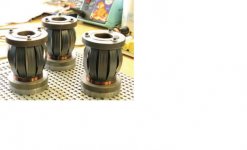 Mbl naked mids 3.jpg27.9 KB · Views: 804
 -
 mbl parts.jpg21.2 KB · Views: 803
 -
 mbl_rundstralere_11.jpg127.5 KB · Views: 821
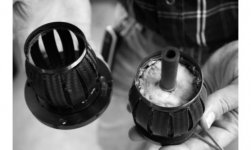
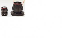
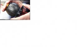
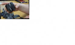
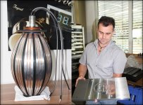
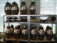
The Melon
Pictures of the Melon naked
Pictures of the Melon naked
Attachments
-
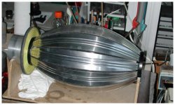
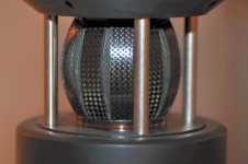
 mbl melon naked and finished.jpg24.5 KB · Views: 190
 -
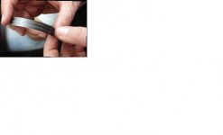
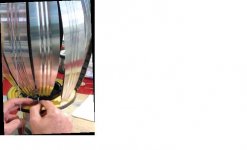
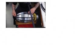 mbl melon the black elastic bands are being put on and so is external dampening.jpg20 KB · Views: 121
 -
 Mbl Naked 6.JPG152.3 KB · Views: 183
 -
 mbl-f557x334-ffffff-C-bee8e138-51568969.jpg30 KB · Views: 195
 -
 Mbl melon naked 7.jpg38.4 KB · Views: 248
 -
 mbl melon naked 3.JPG155.6 KB · Views: 215
 -
 Mbl melon lamnella after rolled corrigation.jpg14.2 KB · Views: 145
 -
 Mbl melon lamnella after dampening has been applied.jpg14.9 KB · Views: 181
 -
 Mbl melon lamnella.jpg34.9 KB · Views: 190
 -
 mbl melon beinge flued to thrust plate and motor sytem.jpg25 KB · Views: 265
Additional pics
Additional pictures that weren't able to be put into the other post due to attachment limits.
Additional pictures that weren't able to be put into the other post due to attachment limits.
Attachments
-
 Mbl Nice Shot Of mid 2.jpg222.7 KB · Views: 201
 -
 mbl-f557x334-ffffff-C-a25ca6b-51568970.jpg38.6 KB · Views: 230
 -
 mbl_rundstralere_7.jpg161.3 KB · Views: 268
 -
 mbl outline.GIF12.1 KB · Views: 209
 -
 Mbl naked melons 8.jpg21.7 KB · Views: 113
 -
 Mbl naked cab.jpg17.6 KB · Views: 142
 -
 mbl naked 4.JPG158.2 KB · Views: 172
 -
 Mbl Melon naked.jpg288.1 KB · Views: 156
 -
 mbl-116F-Elegance-f557x334-ffffff-C-42ba959e-51576290.jpg27.1 KB · Views: 177
Well my goal for this summer break is to at least get the mid-range driver completed. I don't think i will be needing to out source many of the parts, Since I have a friend with a high grade cnc machine at his disposal. Although yes the end goal is to have replicated the entire thing.I think Seth's head just exploded!
So, you are planning to replicate the entire thing? Not outsourcing any parts of it? Hope you don't require much sleep, cause summer break is not a long time to get this worked out.
Greg
Mbl Magnetic circuit
I know this is going to sound silly, but can anyone tell me how the drivers work. If you look at the naked pictures of both the mid and tweeter there's only 2 pieces of materiel.
The only speaker motor that i know of is a sandwich construction. with either a overhung or under-hung topology.tihe the mbl the v-c looks to be literally standing on the magnetic motor structure. Anyone got any ideas?
Looks to be a straight forward magnetic circuit with a standard voice coil - looks very overhung - on the end of the "melon" petals... the VC pumps up and down and the petals move in and out in response...
otoh the VC may be pushed into the gap when the unit is assembled... gotta look closely at the pix, I haven't yet.
If you look at the Walsh (Ohm F) driver, it is really quite similar except the "cone" on the MBL is different...
The MBL is frightfully low in sensitivity, so be sure to max your magnetics and get the gap right...
I'd be concerned about the VC moving linearly in the gap, having seen how they assemble it. Very surprising to me that they seem to attach the "petals" to the VC former after the petals are connected to the opposite side. I would have expected to do it in the reverse fashion...
Also I am surprised at the damping material on the reverse side of the bass petals, and the fill inside the midrange...
seems to me that forming the petals accurately is going to be a bit of a difficult thing to do, and essential to the operation of the driver as well...
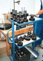
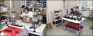
where did you find the pix of the manufacturing process?
Guess MBL is daring anyone to try it themselves!!
Please do post your progress, successful or not!!
_-_-bear
otoh the VC may be pushed into the gap when the unit is assembled... gotta look closely at the pix, I haven't yet.
If you look at the Walsh (Ohm F) driver, it is really quite similar except the "cone" on the MBL is different...
The MBL is frightfully low in sensitivity, so be sure to max your magnetics and get the gap right...
I'd be concerned about the VC moving linearly in the gap, having seen how they assemble it. Very surprising to me that they seem to attach the "petals" to the VC former after the petals are connected to the opposite side. I would have expected to do it in the reverse fashion...
Also I am surprised at the damping material on the reverse side of the bass petals, and the fill inside the midrange...
seems to me that forming the petals accurately is going to be a bit of a difficult thing to do, and essential to the operation of the driver as well...
where did you find the pix of the manufacturing process?
Guess MBL is daring anyone to try it themselves!!
Please do post your progress, successful or not!!
_-_-bear
The pictures of the manufacturing process were found after days searching on the web finding literally all i could.. I will surely be posting progress updates but before that i am still learning about FEMM and magnetic circuit design. Also Mbl states that the other end opposing the V-C is attached to a thrust bearing what exactly would this add?Looks to be a straight forward magnetic circuit with a standard voice coil - looks very overhung - on the end of the "melon" petals... the VC pumps up and down and the petals move in and out in response...
otoh the VC may be pushed into the gap when the unit is assembled... gotta look closely at the pix, I haven't yet.
If you look at the Walsh (Ohm F) driver, it is really quite similar except the "cone" on the MBL is different...
The MBL is frightfully low in sensitivity, so be sure to max your magnetics and get the gap right...
I'd be concerned about the VC moving linearly in the gap, having seen how they assemble it. Very surprising to me that they seem to attach the "petals" to the VC former after the petals are connected to the opposite side. I would have expected to do it in the reverse fashion...
Also I am surprised at the damping material on the reverse side of the bass petals, and the fill inside the midrange...
seems to me that forming the petals accurately is going to be a bit of a difficult thing to do, and essential to the operation of the driver as well...
where did you find the pix of the manufacturing process?
Guess MBL is daring anyone to try it themselves!!
Please do post your progress, successful or not!!
_-_-bear
Last edited:
On the bass "melon"? A thrust bearing??
Perhaps a mistranslation from the German?
I would think that over there is more or less a hinge, so that the bending motion is not impeded by stiffness. So, the hinge would need to have stiffness in the vertical direction (the way that the VC is pushing - that vector) but be able to bend outward to permit free flexing of the petals... or not. Pure conjecture.
It might be marketing hype too... the connection to the VC would likely be the *same* as the connection on the top.
educated guesses... or uneducated blabbering... either way about the same value?
_-_-bear
Me too i'am tring to replicate it...after 3 years of R&D i realized mid and tweeter.
Quite sadisfay, but an updated version is ready to be realized ..
I am involved in woofer contsruction at the moment....
and i just wonder where did you read that the aluminum lamella are made of 2 pieces glued togheter?
Thikness?
Quite sadisfay, but an updated version is ready to be realized ..
I am involved in woofer contsruction at the moment....
and i just wonder where did you read that the aluminum lamella are made of 2 pieces glued togheter?
Thikness?
Attachments
Wow, difficult project , getting the mechanicals right will almost be as difficult as getting them to sound right , then of course the amplification necessary to power them to reasonable levels .. May I suggest laminated foil until you get the mechanicals right , before attempting carbon diaphragms..
MBL has been at this speaker for decades , the early ones where soft and delicate sounding ,
good luck !!!

MBL has been at this speaker for decades , the early ones where soft and delicate sounding ,
good luck !!!
On the bass "melon"? A thrust bearing??
Perhaps a mistranslation from the German?
I would think that over there is more or less a hinge, so that the bending motion is not impeded by stiffness. So, the hinge would need to have stiffness in the vertical direction (the way that the VC is pushing - that vector) but be able to bend outward to permit free flexing of the petals... or not. Pure conjecture.
It might be marketing hype too... the connection to the VC would likely be the *same* as the connection on the top.
educated guesses... or uneducated blabbering... either way about the same value?
_-_-bear
Actually the gap where the lamellas are fixed has to be large enough to permit them to vibrate. The trick is to choose the correct glue. Mbl is supposed to use a silicone rubber glue. Furthermore, is very important that does exist an axial rigid connection to the thrust bearing, otherwise it works as a low pass filter.
I touched the lamellas wilhe the loudspeaker was sounding and it doesn't have a large excursion...as expeted.
Magnasanti
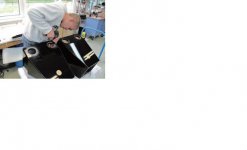
Interesting photo of what looks like an MBL midbass prototype..
http://img.photobucket.com/albums/v53/eliot/sommar07/mbl063.jpg
By the way, could you please provide the link or links that the assembly photos came from? I tried to find them on my own, but had no success..
Seth
Interesting photo of what looks like an MBL midbass prototype..
http://img.photobucket.com/albums/v53/eliot/sommar07/mbl063.jpg
By the way, could you please provide the link or links that the assembly photos came from? I tried to find them on my own, but had no success..
Seth
Last edited:
LOTS of sites AND brochures as well from review sites they took along time to get. I could however point you in a general direction. Try searching for jurgen reis mbl (IMAGE), and a good one is mbl 101 PDF.Ill provide some links anyway it would be a pain in the **** to go find every pic again through the web so here are some links. https://www.google.com/search?q=mbl....,cf.osb&fp=5f551c48dd37d1b2&biw=1280&bih=601Magnasanti
Interesting photo of what looks like an MBL midbass prototype..
http://img.photobucket.com/albums/v53/eliot/sommar07/mbl063.jpg
By the way, could you please provide the link or links that the assembly photos came from? I tried to find them on my own, but had no success..
Seth
Last edited:
- Status
- This old topic is closed. If you want to reopen this topic, contact a moderator using the "Report Post" button.
- Home
- Loudspeakers
- Planars & Exotics
- Summer Project - Replication of MBL loudspeaker 101mkII