Hi I'm new here from HeadFi. I figured this was the best place to ask because i've seen a lot of full sized speaker builds using planar tech but has anybody made maybe a 80mm orthodynamic driver for a custom set of headphones? It seems that tiny rectangular neodymium are actually pretty inexpensive to obtain in the US which is where i am. To me the tricky part seems like making a diaphragm that tiny. Could it be done with an ESL approach to the diaphragm by using a conductive coating? or does it absolutely have to be a conductive wire? I've only just gotten into Ortho's and ESL but it really interests me and i'm a pretty handy DIY'er. Any advice would be greatly appreciated. thank you
-Sean
-Sean
I'm probably not the best to answer your questions, but certain areas of this forum seem pretty, well, impatient with guys like us (limited knowledge). Being in a similar boat as you I figured I'd respond and hope to be of some help. Maybe we can draw some attention and get the older, more experienced members to whip our mindsets into shape, who knows?
The magnetic field is created per the direction of current in your conductor. If you wanted to use a "coating" I'm imagining some sort of conductive ink that you'd be printing onto the substrate which then leaves me questioning the power handling of said conductive ink/coating, heat dissipation, reliability, etc. An expensive route requiring job specific equipment with pretty up in the air results for a one-off, imo.
Those tiny cube magnets would be hell to check the polarity, orient directionally, and then somehow glue or clamp in place. You'd basically be making standard bar magnets with hundreds of tiny 5mm^3 pieces which seems like a lot of hassle for what it'd save you in cost. That said this patent could maybe put good use to those tiny cubes if you took the time to measure everything out perfectly, although that's an extremely ambitious design for a first-time DIY planar magnetic project. It sure drives me away.
Capacitor foil could be etched into the desired circuit design. It's very close to what I'd consider near optimum for a diaphragm material. ER Audio also sells Aluminized tweeter foil that might be right up your alley with a similar idea in mind. If you didn't want to etch it yourself RFID's are scary close to what you'd be trying to create so if you can find a place that's in both the foil and RFID business that can create a polymer film per your spec and "print" the desired artwork >>in small runs and for cheap<< you'll have to tell me who they are because I'd really like to know. I'd imagine most places are looking at 10k+ feet and thousands of dollars as a minimum order, and that's if you can find a place that's even willing to humor something that specific and short of a run.
Head-Fi member Setmenu made his own ribbon drivers. Have you seen that? Most of the pictures are dead and information is strewn between multiple threads, but other people saved/hosted a few snap shots of the second gen carbon fiber prototypes that he got running and it was all very interesting to read about and see.
I have a pair of Technics EAH-820 and a pair of Peerless PMB-100 orthydynamic headphones. The Technics can be taken apart (I did). The diaphragm has an aluminium layer etched, which is difficult to reproduce. You can see it in this other thread:
Technics EAH-830
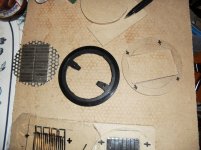
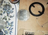
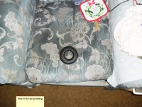
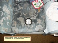
Also the magnets are flat ferrites with holes, and an alternating pole magnetism. There are paper spacers, and the plastic frame holds all together. The magnets are mounted in a repelling fashion against each other, so that the flux lines are parallel to the diaphragm, perpendicular to the wires.
You can buy such and other old headphones cheap on eBay, there is no sense to build one IMHO.
Technics EAH-830
Also the magnets are flat ferrites with holes, and an alternating pole magnetism. There are paper spacers, and the plastic frame holds all together. The magnets are mounted in a repelling fashion against each other, so that the flux lines are parallel to the diaphragm, perpendicular to the wires.
You can buy such and other old headphones cheap on eBay, there is no sense to build one IMHO.
PLANAR HEADPHONES.
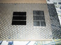
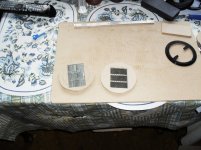
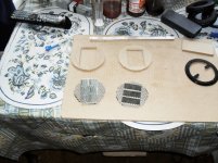
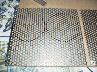
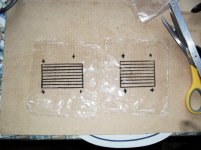
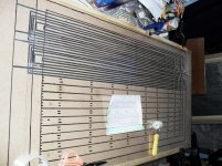
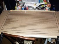
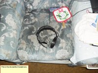
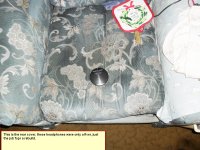
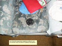
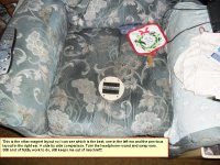
I did start a planar headphone using an old headphone I had,using 2 different magnet layouts, but got sidetracked with something else. Never finished them. See photos!
I did start a planar headphone using an old headphone I had,using 2 different magnet layouts, but got sidetracked with something else. Never finished them. See photos!
Attachments
-
 SAM_0176.JPG937.8 KB · Views: 727
 -
 SAM_0187.JPG679.1 KB · Views: 238
 -
 SAM_0186.JPG627 KB · Views: 252
 -
 SAM_0185.JPG734.6 KB · Views: 251
 -
 SAM_0183.JPG716.6 KB · Views: 234
 -
 SAM_0182.JPG765.8 KB · Views: 581
 -
 SAM_0179.JPG826 KB · Views: 597
 -
 SAM_0178.JPG871.6 KB · Views: 634
 -
 SAM_0177.JPG888.4 KB · Views: 663
 -
 SAM_0188.JPG730.6 KB · Views: 266
SOME MORE PHOTOS
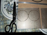
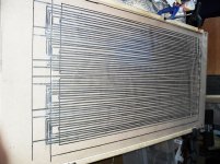
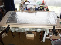
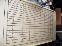
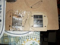
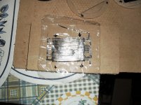
They are very fiddly to stick the foil to the thin diaphragm, especially at my age(73)!! It's easier with the full size diaphragms, although it does get harder when you use 6 um mylar!!!
They are very fiddly to stick the foil to the thin diaphragm, especially at my age(73)!! It's easier with the full size diaphragms, although it does get harder when you use 6 um mylar!!!
Attachments
-
 SAM_0205.JPG769.4 KB · Views: 195
 -
 SAM_0204.JPG726 KB · Views: 188
 -
 SAM_0203.JPG767.7 KB · Views: 188
 -
 SAM_0197.JPG766.2 KB · Views: 193
 -
 SAM_0201.JPG745.7 KB · Views: 161
 -
 SAM_0193.JPG780.5 KB · Views: 168
 -
 SAM_0192.JPG811.7 KB · Views: 165
 -
 SAM_0191.JPG846.8 KB · Views: 199
 -
 SAM_0190.JPG794.2 KB · Views: 413
 -
 SAM_0189.JPG756.9 KB · Views: 277
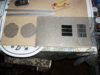
Henry: That looks awesome. Got a couple questions, though. What's up with your circuit layout? I'm trying to follow it and it looks like you've got current running opposite directions in very near proximity. Also, you planned on only having magnets on the rear, correct?
Anyway, really cool and I hope you finish the project. Ear speakers like a Stax Sigma could be interesting taking this route, imo.
Anyway, really cool and I hope you finish the project. Ear speakers like a Stax Sigma could be interesting taking this route, imo.
very interesting design, so you were going to have magnets on only 1 side of the headphones as well? also what is the foil in the diaphragm made of? and one more question, please excuse my ignorance for i'm trying to learn, but why push all of the magnets together so close? on most planar headphones i've seen the magnets are much more spaced out
Back to my idea on drivers i was thinking i could cnc an imprint of a very thin serpentine groove into a round block of aluminum then mirror it over to an identical block. Then i'd have the fun time of finding a sturdy conductive and thin wire i can lay in between the sandwiched blocks. after i get a good fit and the wire bent into shape i could find a polyester sheet maybe 3 microns thick that can be thermally bound. place the polyester on the face of each aluminum block and press the wire between them. after that all i'd have to do is heat the aluminum hot enough to bond the sheets of ployester and there you have it. does this sound logical? or am i missing something crucial.
Back to my idea on drivers i was thinking i could cnc an imprint of a very thin serpentine groove into a round block of aluminum then mirror it over to an identical block. Then i'd have the fun time of finding a sturdy conductive and thin wire i can lay in between the sandwiched blocks. after i get a good fit and the wire bent into shape i could find a polyester sheet maybe 3 microns thick that can be thermally bound. place the polyester on the face of each aluminum block and press the wire between them. after that all i'd have to do is heat the aluminum hot enough to bond the sheets of ployester and there you have it. does this sound logical? or am i missing something crucial.
very interesting design, so you were going to have magnets on only 1 side of the headphones as well? also what is the foil in the diaphragm made of? and one more question, please excuse my ignorance for i'm trying to learn, but why push all of the magnets together so close? on most planar headphones i've seen the magnets are much more spaced out
Back to my idea on drivers i was thinking i could cnc an imprint of a very thin serpentine groove into a round block of aluminum then mirror it over to an identical block. Then i'd have the fun time of finding a sturdy conductive and thin wire i can lay in between the sandwiched blocks. after i get a good fit and the wire bent into shape i could find a polyester sheet maybe 3 microns thick that can be thermally bound. place the polyester on the face of each aluminum block and press the wire between them. after that all i'd have to do is heat the aluminum hot enough to bond the sheets of ployester and there you have it. does this sound logical? or am i missing something crucial.
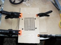
Yes only one layer, aluminium foil cut to size with scissors2.25 mm wide, started out as 9 mm wide burglar tape from CPC. Easier to place magnets on perforated steel sheet otherwise you have to glue,if you use gaps. Which I have tried on bigger planars, never again.Also you get more control and more sensitivity, especially in the bass. The bass on my planars is tighter and more solid than the bass on quad 57's and 63's, I have both and was very disappointed with the plummy and resonant bass. I would just stick the foil on mylar, as I do with all my designs, have built over 30 full range planars using foil. Done a few more rebuilds with thinner mylar (down to 6 um), and different layouts. The latest being the epsilon layout using both ferrites and neos of different widths and thickness. Started 20 years ago, and I am still learning and rebuilding. Keeps me busy and keeps my brain working.All the best.
Last edited:
very interesting design, so you were going to have magnets on only 1 side of the headphones as well? also what is the foil in the diaphragm made of? and one more question, please excuse my ignorance for i'm trying to learn, but why push all of the magnets together so close? on most planar headphones i've seen the magnets are much more spaced out
Back to my idea on drivers i was thinking i could cnc an imprint of a very thin serpentine groove into a round block of aluminum then mirror it over to an identical block. Then i'd have the fun time of finding a sturdy conductive and thin wire i can lay in between the sandwiched blocks. after i get a good fit and the wire bent into shape i could find a polyester sheet maybe 3 microns thick that can be thermally bound. place the polyester on the face of each aluminum block and press the wire between them. after that all i'd have to do is heat the aluminum hot enough to bond the sheets of ployester and there you have it. does this sound logical? or am i missing something crucial.
Yes only one layer, aluminium foil cut to size with scissors2.25 mm wide, started out as 9 mm wide burglar tape from CPC. Easier to place magnets on perforated steel sheet otherwise you have to glue,if you use gaps. Which I have tried on bigger planars, never again.Also you get more control and more sensitivity, especially in the bass. I would just stick the foil on mylar, as I do with all my designs, have built over 30 full range planars using foil. Done a few more rebuilds with thinner mylar (down to 6 um), and different layouts. The latest being the epsilon layout using both ferrites and neos of different widths and thickness. Started 20 years ago, and I am still learning and rebuilding. Keeps me busy and keeps my brain working.All the best.
So you like the closed back planar sound better than open back? the reason i say it is there isn't much room to work with in the rear if you want to open the back up, unless im not seeing your design right? I'm referring to the headphones by the way, but you still like the one sided magnet design better?
I didn't finish the headphone designs, so can't say if I like it in comparison with the open back design! All my other designs of full sized full range planars only use the one sided designs. I did build 2 sided designs but gave up on those because the extra cost and build wasn't worth the effort, as I found out. You live and learn,So you like the closed back planar sound better than open back? the reason i say it is there isn't much room to work with in the rear if you want to open the back up, unless im not seeing your design right? I'm referring to the headphones by the way, but you still like the one sided magnet design better?
 and I'm still learning after 20 years of effort!!
I didn't finish the headphone designs, so can't say if I like it in comparison with the open back design! All my other designs of full sized full range planars only use the one sided designs. I did build 2 sided designs but gave up on those because the extra cost and build wasn't worth the effort, as I found out. You live and learn,So you like the closed back planar sound better than open back? the reason i say it is there isn't much room to work with in the rear if you want to open the back up, unless im not seeing your design right? I'm referring to the headphones by the way, but you still like the one sided magnet design better?
and I'm still learning after 20 years of effort!!CONTINUATION OF PLANAR HEADPHONE DESIGN
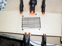
Have done some more work on the headphone I started a while back. Have sorted out method of fixing with old headphone I dismantled. So just a matter of time and enthusiasm needed to finish the project. Have to be in the mood.

Have done some more work on the headphone I started a while back. Have sorted out method of fixing with old headphone I dismantled. So just a matter of time and enthusiasm needed to finish the project. Have to be in the mood.
Attachments

?.004 - YouTube
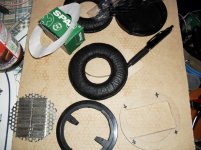
You mean like this?
It actually sounded okay at one point, but I burned out the driver trying to get uhh a more reasonable output volume. They were not sensitive enough at all. I have many things I would like to try to increase the sensitivity but I've been sidetracked and haven't worked on this driver since december. I have not even thought about a housing yet, only done work on the driver. I'm not sure if the video was shot after burning out the driver or before and it just sounds like crap because of the cell phone. The contacts were not sturdy enough for a real headphone either but this was just an early prototype so to speak. Hard to really say much except it sounded okay because it was fairly quiet and the best I could really do without risking breaking the contacts for the diaphragm was to lay down next to it.
Anyone got any experience with modeling magnetic fields of permanent magnets? :/
Anyone got any experience with modeling magnetic fields of permanent magnets? :/
Do a search for FEMM. It's probably your best bet for modeling static magnetic fields without a large financial investment.
Sean: I'd recommend trying narrow strips of aluminum foil rather than wire but that's not based on extensive experience with both approaches. The foil provides more surface area for adhesion, which can be an advantage. It also minimizes the amount of undriven diaphragm area, all else being equal. Gaining some experience with simpler models that don't require the machining of the aluminum blocks etc. would likely get you to a satisfactory point quicker. Often the low tech hurdles are the toughest to surmount so it probably makes sense to solve the more esoteric issues after the basics are well in hand.
Absolutely no disrespect intended regarding Jamesbos's extensive and impressive work, but I'd suggest reading up on the diyaudio threads discussing the Epsilon layout before diving in head first. There's some disagreement about which aspects of the Epsilon design achieve which ends.
Keep us posted.
Few
Thought it might be worth a try reviving this thread!
I'm seriously contemplating giving this a shot. I think the aluminium conductor could be pretty well sorted out through etching. I think ferric chloride will do the trick.
I've looked into etching brass and whatnot lately and found a method for transferring designs to metal. What you basically do is use a laser printer and print your design (mirrored!) on glossy paper, could be just a page from an old magazine. You then proceed to clean you aluminium foil and use a clothes iron on high temperature and lots of pressure to transfer the design to the foil. Only the pigment from the laser printer will stick so don't worry about there already being printing on the page. When etching later on the pigment will act as a protective coating.
The use for foil is in theory but I've seen it used successfully on thicker materials. Next step is that you glue the entire sheet of foil onto the material you want to use as a diaphragm (I assume this might be a problem through adding thickness to the membrane). Next step: suspend your diaphragm, face down, in ferric chloride.
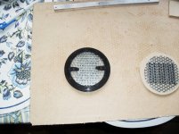
Looking at some of the older designs they seem to use ferric magnets, plates with holes drilled in them. That goes for the ones with circular membranes and the spiral conductor. Is the same system of alternating polarity used on those? Or is it thought that the wire will run perpendicular to the field lines as they are going in spiral?
Best
/Karl
I'm seriously contemplating giving this a shot. I think the aluminium conductor could be pretty well sorted out through etching. I think ferric chloride will do the trick.
I've looked into etching brass and whatnot lately and found a method for transferring designs to metal. What you basically do is use a laser printer and print your design (mirrored!) on glossy paper, could be just a page from an old magazine. You then proceed to clean you aluminium foil and use a clothes iron on high temperature and lots of pressure to transfer the design to the foil. Only the pigment from the laser printer will stick so don't worry about there already being printing on the page. When etching later on the pigment will act as a protective coating.
The use for foil is in theory but I've seen it used successfully on thicker materials. Next step is that you glue the entire sheet of foil onto the material you want to use as a diaphragm (I assume this might be a problem through adding thickness to the membrane). Next step: suspend your diaphragm, face down, in ferric chloride.
Looking at some of the older designs they seem to use ferric magnets, plates with holes drilled in them. That goes for the ones with circular membranes and the spiral conductor. Is the same system of alternating polarity used on those? Or is it thought that the wire will run perpendicular to the field lines as they are going in spiral?
Best
/Karl
- Status
- This old topic is closed. If you want to reopen this topic, contact a moderator using the "Report Post" button.
- Home
- Loudspeakers
- Planars & Exotics
- DIY Orthodynamic drivers? (for headphones!)