Hi,
I'm having a sensitivity "problem" with a full ranger ESLs. Their specs are:
- The radiating area is approx 67cm x 200cm
- Panels' capacitance is around 2,7nF
- 45-49% open area carbon steel stators
- Step-up trafo is 1:75 from Plitron
- D/S spacing is 3-3.5mm
- bias supply is variable between 3.5 ... 7kV
- there is a 100meg HV resistor in series with the membrane
- membrane is aluminum coated mylar
- Polycarbonate/acryl spacers
- Nylon screws clamp the stators together
The measured sensitivity is around 75dB/2.83Vrms/1kHz/1m with ~5kV bias, which seems very low for this big stats. I measure the sensitivity in my room, so room modes affect the readings, I can get the readings peak at ~78dB if I keep changing the meter's place in front of the speaker. Membranes do not leak, the "Quad light bulb tweak" flashes in every ~3-4 seconds.
I would much appreciate speculation of possible reasons for low sensitivity. The DC bias on the membrane is somehow lower that it should be, some cancellation between the stators, the step-up trafo cannot drive capacitance this big or, or...?
Or are these readings norrmal and I just have to increase the step-up ratio in order to get more sensitivity?
Regards,
Legis
Last edited:
Hi,
The low sensitivity of your setup can easily be because of relatively large diaphragm - stator spacing and somewhat low step-up ratio.
1 : 75 is in my opinion more suited to a D/S spacing of around 1 mm.
5 kV bias is also not much for a 3 mm spacing.
Another possible source of problems is diaphragm not charged fully - problem with coating.
However in my opinion 75 db/1W is about to be expected in your case with step up ratio and voltages you mentioned.
Regards,
Lukas.
Last edited:
In my experience, verifying that your ESLs are putting out the SPL they should be based on Vbias, Vsig, and diaphragm to stator spacing is best done with a NF(near field) measurement at the center of the panel. Note that panel size(height and width) does not figure into the calculation.
P = e0*Vbias*Vsig/d^2
SPL(NF) = 20*LOG(P/.00002) – 6
Where:
P = sound pressure (N/m^2)
e0 = vacuum permittivity = 8.8e-12 (F/m)
Vbias = bias voltage
Vsig = signal voltage applied between stators
d = diaphragm to stator spacing (m)
So, for your case:
P = (8.8e-12)*5000*(2.83*75)/(.003)^2 = 1.0377
SPL(NF) = 20*LOG(1.0377/.00002) – 6 = 88.3 dB
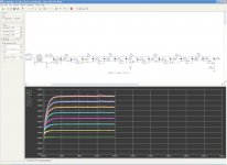
Alternatively, you can use arend-jan’s handy calculator for the generalized Walker equation:
Electrostatic Loudspeaker (ESL) Simulator
Attachment shows resulting summations match very well with theoretical calculation above.
The 75dB you mention measuring at 1m sounds a little low to me, but not that far off.
See what SPL you measure 1cm away from the middle of your panel.
If all is working well, you should expect to see output about -2dB to -3dB below theoretical output of 88.3dB.
BTW, what microphone measurement setup are you using? Have you checked its calibration with a known source?
================================
More discussion on this topic here:
http://www.diyaudio.com/forums/planars-exotics/199943-measuring-sensitivity-esls.html
================================
.
P = e0*Vbias*Vsig/d^2
SPL(NF) = 20*LOG(P/.00002) – 6
Where:
P = sound pressure (N/m^2)
e0 = vacuum permittivity = 8.8e-12 (F/m)
Vbias = bias voltage
Vsig = signal voltage applied between stators
d = diaphragm to stator spacing (m)
So, for your case:
P = (8.8e-12)*5000*(2.83*75)/(.003)^2 = 1.0377
SPL(NF) = 20*LOG(1.0377/.00002) – 6 = 88.3 dB
Alternatively, you can use arend-jan’s handy calculator for the generalized Walker equation:
Electrostatic Loudspeaker (ESL) Simulator
Attachment shows resulting summations match very well with theoretical calculation above.
The 75dB you mention measuring at 1m sounds a little low to me, but not that far off.
See what SPL you measure 1cm away from the middle of your panel.
If all is working well, you should expect to see output about -2dB to -3dB below theoretical output of 88.3dB.
BTW, what microphone measurement setup are you using? Have you checked its calibration with a known source?
================================
More discussion on this topic here:
http://www.diyaudio.com/forums/planars-exotics/199943-measuring-sensitivity-esls.html
================================
.
Attachments
....
The 75dB you mention measuring at 1m sounds a little low to me, but not that far off.
See what SPL you measure 1cm away from the middle of your panel.
If all is working well, you should expect to see output about -2dB to -3dB below theoretical output of 88.3dB.
BTW, what microphone measurement setup are you using? Have you checked its calibration with a known source?
...
Hi bolserst, thanks for the info. The result came out 75-81dB right next to the front stator (2.83Vrms/1kHz). The big tolerance is because of the room, the readings varied greatly by changing the meter's position. The SPL meter I'm using is digital Radioshack, it should be fairly accurate between 50Hz and 1kHz according to a measurement I once saw floating around the Internet. I also have uncalibrated EMC8000.
Last edited:
Hello Legis,The result came out 75-81dB right next to the front stator (2.83Vrms/1kHz). The big tolerance is because of the room, the readings varied greatly by changing the meter's position. The SPL meter I'm using is digital Radioshack, it should be fairly accurate between 50Hz and 1kHz
I think you are saying that you are still getting big changes in NF(near field) SPL readings with small changes in mic position which you are attributing to room modes. You could try repeating the measurement outside to test this theory, or try some other frequencies from 500Hz – 1Khz to see if this helps with possible room mode issue. SPL should be the same. If you do try measuring outdoors, you might consider bumping up the signal level by a factor of 2 or 4 to boost output by 6dB or 12dB to raise the output a bit more above ambient noise level.
Assuming your 81dB measurement is correct, this is a bit lower than I would have expected.
The discrepancy could be related to the panel, or the measurement technique.
Questions concerning your panel:
- I used D/S = 3mm when estimating the output level. I just noticed you specified a tolerance of 3mm – 3.5mm. A 3.5mm panel with 5kV bias would have a theoretical NF output level of 85.6dB. So, you can see that small changes in D/S will change the output level significantly. Can you estimate the D/S more accurately?
- What are your stators coated with, and how thick is the coating? Thicker coatings and ones with lower dielectric constant and higher bulk resistivity will lower the SPL more than the 2 – 3dB I estimated.
- a common reason for low SPL is poorly conducting diaphragms or leakage. But, you mention aluminum coated mylar and a slow blinking charge indicator. The only problem you could have here is if the diaphragm contact is poor.
- how are you measuring your bias voltage? are you confident the 5kV is accurate.
Questions concerning measurement technique:
- Yes, the digital RS meter is known to yield fairly accurate SPL readings below 1kHz. Were you using the “C” weighting setting? At 1khz it shouldn’t change much with the other settings, but you might check it if you were using the “A” weighting setting.
- How are you measuring/setting the 2.83Vrms level?
Oh, I forgot to ask, are your panels flat? or curved/faceted.
Last edited:

Questions concerning your panel:
- I used D/S = 3mm when estimating the output level. I just noticed you specified a tolerance of 3mm – 3.5mm. A 3.5mm panel with 5kV bias would have a theoretical NF output level of 85.6dB. So, you can see that small changes in D/S will change the output level significantly. Can you estimate the D/S more accurately?
- What are your stators coated with, and how thick is the coating? Thicker coatings and ones with lower dielectric constant and higher bulk resistivity will lower the SPL more than the 2 – 3dB I estimated.
- a common reason for low SPL is poorly conducting diaphragms or leakage. But, you mention aluminum coated mylar and a slow blinking charge indicator. The only problem you could have here is if the diaphragm contact is poor.
- how are you measuring your bias voltage? are you confident the 5kV is accurate.
Questions concerning measurement technique:
- Yes, the digital RS meter is known to yield fairly accurate SPL readings below 1kHz. Were you using the “C” weighting setting? At 1khz it shouldn’t change much with the other settings, but you might check it if you were using the “A” weighting setting.
- How are you measuring/setting the 2.83Vrms level?
Oh, I forgot to ask, are your panels flat? or curved/faceted.
Hi, the panels are curved. The spacers are 3mm thick so one can use that in the calculations although the membrane is segmented into vertical strips and the membrane is closer to the back stator than the front in the middle of each vertical segment. I quess the electrostatic force should be quite equal between the stators regardless that the membrane is not constantly right in the middle of them.
The stators are double powder coated with epoxy based deep shiny black powder coat and there is sprayed 2.1kV/mil epoxy based conformal coating on the backside (the side facing the membrane) of the stator for extra insulation. Maybe couple of mils of the conformal coating, but I'm planning to add some more.
The contact to the membrane is done by soldering the lead to a copper tape, that has conductive glue, and it has been glued to the membrane.
I have not actually measured the bias voltage, in that I'm counting on the person who made the bias supplies.
I measured the SPL with C-weighting, "max" setting and fast reaction time (125ms average). The 2.83Vrms is measured with a multimeter, I have checked that it's reading stays constant to several kilohertz, but it does not measure 20kHz sine's amplitude correctly anymore (the reading is lower than it should). The meter is UNI-T UT33A. I also have a 500MHz digiscope but I have trusted the meter to be fairly accurate.
Regards,
Legis
Last edited:
Sounds like you have all your measurement techniques and equipment in good shape, and diaphragm contact isn't an issue.
Two thinks that stick out to me from your description.
1) You don't know for sure what your bias voltage is: Even if you don't have a HV probe, you should be able to get a pretty good idea of what it is by measuring the DC voltage across the first capacitor in the multiplier chain with your DVM, and then multiplying by the number of capacitors in the multiplier. Do you have a picture or schematic of the HV supply?
2) Epoxy powder coating: I am not an expert on powder coating materials for ESL stators, but from reading on this forum I believe Nylon 66 is the powder coating material of choice. Epoxy coatings are not conductive enough and much of your bias supply voltage winds up across the coating rather than in the air gap where you want it. You want a coating that is an insulator, just not a really good one. This may account for the additional 4dB - 5dB discrepancy. You should be able to conteract this by cranking up the bias voltage to compensate.
Hopefully Calvin or one of the other guys with coating experience will chime in with their opinion on epoxy coatings .vs. alternatives.
Sounds like you have all your measurement techniques and equipment in good shape, and diaphragm contact isn't an issue.
Two thinks that stick out to me from your description.
1) You don't know for sure what your bias voltage is: Even if you don't have a HV probe, you should be able to get a pretty good idea of what it is by measuring the DC voltage across the first capacitor in the multiplier chain with your DVM, and then multiplying by the number of capacitors in the multiplier. Do you have a picture or schematic of the HV supply?
This is interesting. The supply is supposed to be variable between 3,5kV - 7kV. I measured the DC voltage accross the first capacitor and it was 122V at the minimum setting and 288V at the maximum setting. The ladder has 10 steps/capacitors. So it seems that the actual voltage range is approx. 1,22kV - 2,88kV? If I did the sensitivity measurement with only 2kV voltage it would explain low sensitivity as the sensitivity should be ~80,28dB at 1cm away from the panel according to the mentioned ESL simulator...
Last edited:
Hi,
Is the multiplier ladder fed with low frequency(50 Hz) current?
If so, the multiplier can be significantly loaded by the input impedance of your voltmeter - even when measured at first stage.
So you can see incorrect reading.
Simulation shows this should be a problem(with 0.01uf caps) if multimeter has an input impedance of 1 megaohm, but in case of 10 megaohms or more the effect is small.
Regards,
Lukas.
Last edited:
Here is a simulation I did of a bias supply that I did the other day.
This is assuming that the input voltage is 230Vrms.
The frequency input has know effect on the voltage results.
With 230v in you should have at least 660v across the first capacitor as you didn't state what your input voltage range is.
For every two diodes (one stage) there is an aprox. 230v X 2.88=662.4v increase.
I like to run as high of a bias I can providing the stator insulation doesn't breakdown.
In which it has happend to me.
I was typically running about 7kv normally and as high as 10kv on some tests and the sensitivity just kept going up and I confirmed an increase of nearly 6db ( or was it 3db I don't remember which one,Sorry My bad) by each doubling of the bias voltage and was why I was trying to withhold a 14kv bias on a 1.8mm D/S.
This proved very difficult but not impossible.
It was my high signal level that my panels had met their demise.
With the data I did mange to write down I got as high as 89db to 91db at 1 meter at 2000HZ with a 5.56Kv bias and a 5vpeak signal into to a 1:256 transformation ratio for a small panel of 3.25" X 9.75" using test tones and noise signals.
It sounds to me that your bias voltage may not be were it should be and if you get it up above 3kv and closer to 5kv you should see the results that you are seeking.
Even though you have much large panels than I increasing the transformation ratio would help a great deal as well, try doubling it with another transformer and see if that helps providing that your amplifier can handle the lower impedance load.
But first get your bias supply issue solved first otherwise the extra drive will be barely noticeable.

jer:
This is assuming that the input voltage is 230Vrms.
The frequency input has know effect on the voltage results.
With 230v in you should have at least 660v across the first capacitor as you didn't state what your input voltage range is.
For every two diodes (one stage) there is an aprox. 230v X 2.88=662.4v increase.
I like to run as high of a bias I can providing the stator insulation doesn't breakdown.
In which it has happend to me.
I was typically running about 7kv normally and as high as 10kv on some tests and the sensitivity just kept going up and I confirmed an increase of nearly 6db ( or was it 3db I don't remember which one,Sorry My bad) by each doubling of the bias voltage and was why I was trying to withhold a 14kv bias on a 1.8mm D/S.
This proved very difficult but not impossible.
It was my high signal level that my panels had met their demise.
With the data I did mange to write down I got as high as 89db to 91db at 1 meter at 2000HZ with a 5.56Kv bias and a 5vpeak signal into to a 1:256 transformation ratio for a small panel of 3.25" X 9.75" using test tones and noise signals.
It sounds to me that your bias voltage may not be were it should be and if you get it up above 3kv and closer to 5kv you should see the results that you are seeking.
Even though you have much large panels than I increasing the transformation ratio would help a great deal as well, try doubling it with another transformer and see if that helps providing that your amplifier can handle the lower impedance load.
But first get your bias supply issue solved first otherwise the extra drive will be barely noticeable.
jer:
Attachments
Last edited:
Hi,
Is the multiplier ladder fed with low frequency(50 Hz) current?
If so, the multiplier can be significantly loaded by the input impedance of your voltmeter - even when measured at first stage.
So you can see incorrect reading.
Simulation shows this should be a problem(with 0.01uf caps) if multimeter has an input impedance of 1 megaohm, but in case of 10 megaohms or more the effect is small.
Regards,
Lukas.
Hi, the caps are 0.01µF but I think the supply's ladder and the trafo are fed by LM4950 with 700-900Hz sine (low-passed square). The multimeter should have 10meg input impedance for DC according to the link I posted.
Let me chime in here a bit. I am the designer and builder of these stats. Currently I am preparing for the Lone Star Audio Fest show so I have limited time to answer questions, but let me attach a schematic of the supply. The oscillator indeed runs at about 800Hz and the jumpers are set into 'high' mode.
Attachments
This is interesting. The supply is supposed to be variable between 3,5kV - 7kV. I measured the DC voltage accross the first capacitor and it was 122V at the minimum setting and 288V at the maximum setting. The ladder has 10 steps/capacitors. So it seems that the actual voltage range is approx. 1,22kV - 2,88kV? If I did the sensitivity measurement with only 2kV voltage it would explain low sensitivity as the sensitivity should be ~80,28dB at 1cm away from the panel according to the mentioned ESL simulator...
Since the input impedance of your DVM is 10Mohm, your measurements and calculations should be correct.
Looks like you have isolated the major cause of the lower than expected sensitivity.
It hit me last night....large curved panels, metalized diaphragm....I had seen a link to a build thread for an ESL just like this.
Atom66 posted it here:
http://www.diyaudio.com/forums/planars-exotics/189238-building-electrostatic-speaker.html
Scanning thru the pages, it appears the final design for the HV supply was documented here:
Building an Electrostatic Speaker
Is this is the HV power supply unit you have? If so, two things you might try.
1) change the high/low jumper setting and re-measure the voltage across the first capacitor to confirm the labeling is correct.
2) I see that the voltage is varied by changing the amplitude of the square wave fed to the low pass filter and amplifier driving the step-up transformer. But, the output voltage is also dependent on the level of +Vcc supplied by the external power adapter which may or may not be regulated. You might measure this DC voltage between +Vcc and ground, then check with the builder to see if it is what he had intended when designing it.
Attachments
1) change the high/low jumper setting and re-measure the voltage across the first capacitor to confirm the labeling is correct.
2) I see that the voltage is varied by changing the amplitude of the square wave fed to the low pass filter and amplifier driving the step-up transformer. But, the output voltage is also dependent on the level of +Vcc supplied by the external power adapter which may or may not be regulated. You might measure this DC voltage between +Vcc and ground, then check with the builder to see if it is what he had intended when designing it.
Hi bolserst, the bias was set to high mode as beun said. The 15VDC supply (rated 1A) is actually regulated so I think it should not be the problem. The power draw of the bias supply + it's supply appears to be below 1 watt, my power consumption meter cannot detect any consumption at all (error should not be over 10% in any inductive or capacitive load), so the 1A current capability is likely very sufficient.
Hi bolserst, the bias was set to high mode as beun said. The 15VDC supply (rated 1A) is actually regulated so I think it should not be the problem. The power draw of the bias supply + it's supply appears to be below 1 watt, my power consumption meter cannot detect any consumption at all (error should not be over 10% in any inductive or capacitive load), so the 1A current capability is likely very sufficient.
Hello Legis,
I see that beun, the designer, has joined the conversation. He should be able to help you track down the discrepancy in the HV output.
If the input(pin 1 to 2) and output(pin 3 to 7) voltages on the driver chip are the same as beun measured during design, you might check the transformer secondaries. Perhaps one of the secondaries has shorted leaving you with 1/2 the voltage output you would expect. Measuring voltage from transformer pins(1 to 2) and (3 to 4) should be similar in magnitude. Low output from one coil would indicate a short.
But, it seems extremely unlikely that both HV supplies had a similar failure at a similar time.
I'll leave it to you guys to sort it out.
@beun,
How did you measure HV output?
Hopefully Legis can reproduce your measurement process.
I can check with the scope what the peak-peak signal voltage is at the output of the transformer. That nicely matches up with the simulation and from that I can deduct the HV-output.
Ok.

What is the peak-to-peak signal level you see at the output of the transformer with the control set to maximum?
Legis should be able to measure Vrms with his DVM and and compare after factoring up by [2 x sqrt(2)].
This will confirm if his HV supplies are operating as intended.
As you said, the final HV-ouput can then be calculated from this information.
It looks like this case is now closed. The reason for lower than expected sensitivity was/is because the bias supply does not output what it should. I measured the supply again today, now at the trafo's output insted of across the first capacitor in the ladder. The results were in accordance to the first measurements I made. Bias set to maximum the output seen at the trafo's secondary is 209.7Vrms. 209.7V x 1.414 x 10 = ~3kV. So I had measured the sensitivity with approx 2.15kV bias insted of 5kV like I though, when I had set the bias setting to halfway.
- Status
- This old topic is closed. If you want to reopen this topic, contact a moderator using the "Report Post" button.
- Home
- Loudspeakers
- Planars & Exotics
- Possible reasons for low sensitivity in a full range ESL