Varying the HF balance should not change the input DCR because the new "C" mod configuration of the capacitors block the HF transformer resistance from being in parallel with the LF transformer and the 1 ohm resistor. So the C mod also slightly (maybe 0.2 ohms) increases the DCR resistance the amp sees over the original interface wiring.
Sorry for an off-topic post.I am new here and I need some quick advice.
I have a pair of Acoustat Model 3's I want to sell but I need to test them. All I have to test them with is a live-sound style amp ( Crown XLS 602 ). The rown is rated at 600 watts RMS @ 4 0hms/channel.
Is it safe to use this amp with these speakers? I don't want to damage them.
I apologize.Thanks for your help in advance.
 jackaljohn, You're new here, but please do not post the same question to multiple threads on the forum. Once is enough. Thanks.
More mods...
OK, been a while, but I have been going back and forth on whether or not I want to keep these...but still playing around with more mods in the meantime...
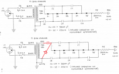
The latest mod is the Bias...I don't know how you can get 5kv from a 750v secondary with a 5x voltage multiplier (seems to me thats no more than 3750v), so I added one more diode and cap to the ladder...I should be at 4500v now... see below - existing and with new 1N4007 diode and a 1000pf 5000V ceramic cap I had laying around...can't really tell if it made a big difference, but I need to listen a little more...It should be easier to drive now with 750v more bias, and louder too...
OK, been a while, but I have been going back and forth on whether or not I want to keep these...but still playing around with more mods in the meantime...
The latest mod is the Bias...I don't know how you can get 5kv from a 750v secondary with a 5x voltage multiplier (seems to me thats no more than 3750v), so I added one more diode and cap to the ladder...I should be at 4500v now... see below - existing and with new 1N4007 diode and a 1000pf 5000V ceramic cap I had laying around...can't really tell if it made a big difference, but I need to listen a little more...It should be easier to drive now with 750v more bias, and louder too...
Attachments
Last edited:
I Add two...your right the bais in all the Acoustats 121 interfaces are low....the best mod i have done to the Acoustat is to get the bias off the mixer board...an set it up so you can set the bias...my setup is from about 4k-6k...your right i can drive my M3s with a 50watt tube amp....I saw you were saleing....these M3 well kill the logans...goodluck
The latest mod is the Bias...I don't know how you can get 5kv from a 750v secondary with a 5x voltage multiplier (seems to me thats no more than 3750v)
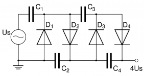
The sections of the voltage multiplier are charged up to the peak of the AC waveform like any other rectified power supply with filter capacitors. The peak of the 750VAC waveform is 750 x sqrt(2) = 750 x 1.414 = 1060Vp.
So, output of the 5x multiplier(assuming no losses) is 1060 x 5 = 5300VDC.
Just setup stock with 5 diodes....an sale them....or cook ever amp you got...an not sound good ...right...if the bias is down the amps sees like a Dead short..Not good for the tranfourmers..
I think that even if there is 5k in the box... it so close to the Mixer setup it get pulled down....what 5k.. it one inch away from the hi-low tranfourmers......Jim would have done this diff but for cost..
I fine it funny that know talks about this...it only the bigest prom with any ESL..if you got a good panel...get the bias right you got the best sound ever....but if the bais is off...low SPL..need a BIG amp...an it still not right the sound is rolled off..base blures...thay just dont sound right...people sale them an that ok more for me...
My Acoustas sounds better than ever...With a good bias....Moray has done this diode mod...Search....goodluck
So, output of the 5x multiplier(assuming no losses) is 1060 x 5 = 5300VDC.
Bolserst,
This is what I always understood...doesn't make it right, but it does jibe with all that have actually tested the output voltage (around 3750v)...doesn't this make sense?
5 x 750VAC = 3750VDC?
Attachments
Last edited:
The sections of the voltage multiplier are charged up to the peak of the AC waveform like any other rectified power supply with filter capacitors. The peak of the 750VAC waveform is 750 x sqrt(2) = 750 x 1.414 = 1060Vp.
So, output of the 5x multiplier(assuming no losses) is 1060 x 5 = 5300VDC.
On paper hes right...I think....?
But i am assuming theres losses...goodluck
Hello john65b,
I think you grabbed your image from wiki page here:
Voltage multiplier - Wikipedia, the free encyclopedia
Note that in the first sentence of the operation section it defines "Us" as the peak voltage of the AC source, not the RMS value. For the Acoustat supply RMS = 750, Peak = 1060.
I have measured many properly working Acoustat HV supplies with Fluke HV probe and the output voltage is as described. If the output measured with a HV probe is much lower than 5kV the answer isn't to add more sections, but to track down the problem which is usually leaky/faulty diodes or capacitors.
As Tyu mentioned, even though Acoustat designed the supply to output 5kV, there can be sound quality advantages to increasing it a bit if your particular panel can handle it without ticking/crackling noises or the diaphragm collapsing to one of the stators. Acoustat used a more conservative HV level that would work for all panels coming out of a production situation.
Yes Yes....i say it lest one can do with A 30year 5k bias... is spend $50 an re-work ea. bais board...these panels are worth it....but most just say these things are hard to drive...the top-end sucks so ...next.. . An as for how Much bias a Acoustat needs there just like the Soundlabs youll hear a buzz when you gone to far...then back of a litte Sweet sound....Long live Acoustats
Thanks for the info bolserst....goodluck
Thanks for the info bolserst....goodluck
I stand corrected... Peak, not RMS...Thanks Bolserst
I wish had a HV probe to test the actual voltage. I have a cheap Craftman Voltmeter that reads up to 1kv, and I have a Varaic, so I set the Variac at 25VAC out to the interface to see if I would get 1/5th the 5kv, but got goofy voltages, once again I forgot my multimeter loading would affect the voltage readings...any other quick way to find a bad cap/diode without actually removing it?
Can I use my cheap Craftman voltmeter across each diode and look for 1050v, or does the probes/meter have to be rated for HV?
Can I use my cheap Craftman voltmeter across each diode and look for 1050v, or does the probes/meter have to be rated for HV?
What is the model number of your voltmeter? Does the instruction manual state what the input impedance is?
If you only have this meter, I would recommend setting the Variac so that the output of the HV transformer measures 100VAC.
Then, switch to DC mode on your voltmeter and:
1) measure the voltage between ground and the output of the ladder network (before the large 500Mohm resistor)
If we know the input impedance of your mulitmeter, we can run spice simulation to determine if your reading indicates trouble in the multiplier.
2) Be sure to perform measurement 1) first so as ensure all capacitors have been discharged thru current draw to a level indicative of the 100VAC input.
Then, measured the DC voltage across each of the capacitors.
Ideally, with no losses and 100VAC input:
C8 = 140 VDC
C6, C7, C9, C10 = 280 VDC (as you work down the chain, these will measure progressively lower due to your meters input imedance)
Let me know what the results are, and I can try and help you decide if there is something wrong with your supply.
OK, I removed the additional diode/cap, so we are back to stock.With 100VAC from bias transformer...
The entire ladder - 109VDC with my 10M Ohm multimeter
Across C8 - 105VDC
Across C6 - 153VDC
Across C9 - 121VDC
Across C7 - 94.3VDC
Across C10 - 81.2VDC
All measurements with Speakers (all three) connected to interface. With C8 only at 100VDC, is D1 dead?
The entire ladder - 109VDC with my 10M Ohm multimeter
Across C8 - 105VDC
Across C6 - 153VDC
Across C9 - 121VDC
Across C7 - 94.3VDC
Across C10 - 81.2VDC
All measurements with Speakers (all three) connected to interface. With C8 only at 100VDC, is D1 dead?
Last edited:
- Status
- This old topic is closed. If you want to reopen this topic, contact a moderator using the "Report Post" button.
- Home
- Loudspeakers
- Planars & Exotics
- Acoustat Model 3 Questions