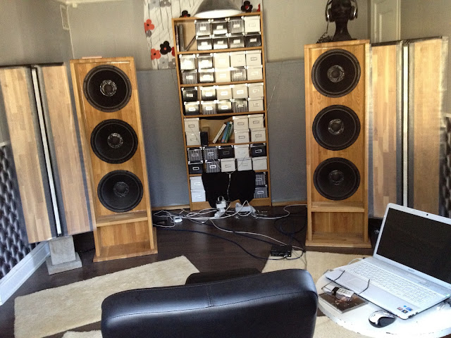
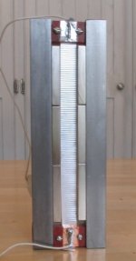
I have 125 cm (49 inches) long ribbons in a open baffle arrangement with 20 cm (8 inches) wide baffles. The baffle is however extended by the side wall at one side and by a h-frame bass column at the other.
I'm in the remaking of the setup, the h-frames will be exchanged with an OB and the ribbons will be more integrated into one baffle.
So I'm currently doing some research on mounting, baffle geometry and such and stumbled across the issue of the actual baffle surface via the EnAbl and felt threads.
I got edge diffraction already covered; the baffle edges will be sloped.
But I cannot get the baffle surface influence on the sound out of my mind...
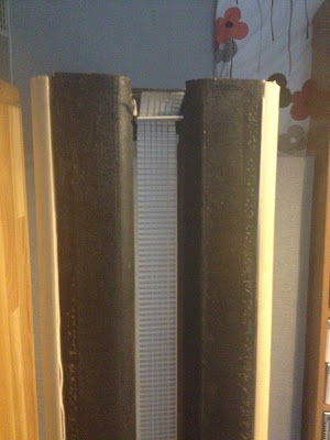
I've started with using a kitchen drawer mat from IKEA:
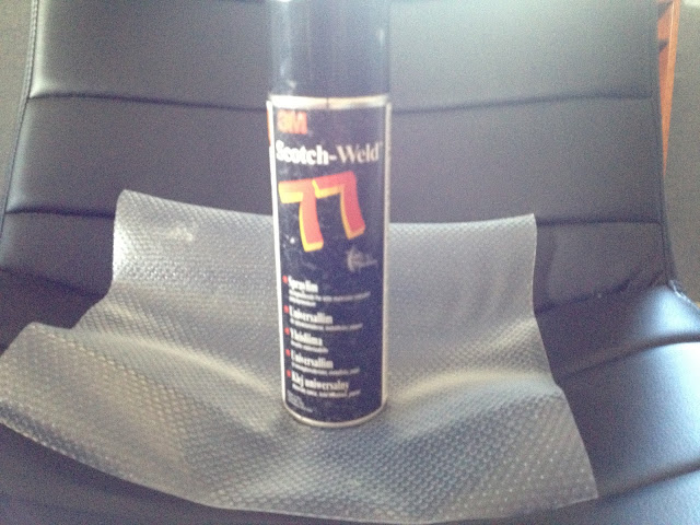
resulting in:
I think I hear some improvement, some instruments is more detailed and so on.
But that could of course be placebo or my listening to the music more intense.
Other ideas is to use highly textured wall paper.
So, what's your verdict? Is this a dead end and will in fact my new setup with edge diffraction taken into consideration prove the baffle surface to be a minor issue?
I'm in the remaking of the setup, the h-frames will be exchanged with an OB and the ribbons will be more integrated into one baffle.
So I'm currently doing some research on mounting, baffle geometry and such and stumbled across the issue of the actual baffle surface via the EnAbl and felt threads.
I got edge diffraction already covered; the baffle edges will be sloped.
But I cannot get the baffle surface influence on the sound out of my mind...
I've started with using a kitchen drawer mat from IKEA:
resulting in:
I think I hear some improvement, some instruments is more detailed and so on.
But that could of course be placebo or my listening to the music more intense.
Other ideas is to use highly textured wall paper.
So, what's your verdict? Is this a dead end and will in fact my new setup with edge diffraction taken into consideration prove the baffle surface to be a minor issue?
Hej!I'm in the remaking of the setup, the h-frames will be exchanged with an OB and the ribbons will be more integrated into one baffle.
Do you mean that the baffle (OB) for the woofers will be the same baffle for the ribbon? (As I could imagine this will reduce the overall width.) If so, I would worry most about keeping woofer vibrations out of the ribbon, and thus make it as stiff and massive as possible....
PS. Is that a pair of AKG K340?
Basically it will be a rude and enlarged clone of the soul sonic design:
I will have a baffle on the ribbon side in order to reach the wall.
On the woofer side, the baffle will be broader and possibly foldable.
Same kind of slope though, using Edge to get the minimal diffraction.
I quad-amp the speakers with one Trimodal driving the ribbons and one GainClone for each woofer. The Gain Clones are fed with the same signal. A modified EMU 0204 (removed attenuator and headphone output stage and replace the OPs with LM4562) is the DAC for a four channel output from Frequency Allocator. Cutoff somewhere between 180 Hz and 400 Hz and otherwise PEQ according to measurements. A PC with J.River Media Center is the source
An externally hosted image should be here but it was not working when we last tested it.
An externally hosted image should be here but it was not working when we last tested it.
I will have a baffle on the ribbon side in order to reach the wall.
On the woofer side, the baffle will be broader and possibly foldable.
Same kind of slope though, using Edge to get the minimal diffraction.
I quad-amp the speakers with one Trimodal driving the ribbons and one GainClone for each woofer. The Gain Clones are fed with the same signal. A modified EMU 0204 (removed attenuator and headphone output stage and replace the OPs with LM4562) is the DAC for a four channel output from Frequency Allocator. Cutoff somewhere between 180 Hz and 400 Hz and otherwise PEQ according to measurements. A PC with J.River Media Center is the source
"Is that a pair of AKG K340?":
Yes, bought some 30 years ago.
I think your instincts were better 30 years ago. What do you not like about the K340? Why not a nice little ESL panel next to your OB woofers? 300-400 xo, perfect. Don't fight the laws of physics; make them work FOR you....
(Because I think you are going in the wrong direction with a wide baffle and also having it against the wall.....)
Hi solhaga,
I get the best soundstage with my dipole linesource ribbon speakers when the ribbons are on the inside of the soundstage and the woofers are on the outside. Having separate bass and tweeter cabinets allows additional soundstage tuning by toe-out of the woofers to use wall bounce to increase the bass delay and reduce room modes, plus toe-in of the ribbons so their vector crosses just in front of the listener position.
A separate shallow H-frame woofer line array can produced good results since it: 1) provides a very sturdy I-beam type construction; 2) the H-frame wings increase bass extension without wasting floor space; 3) the wings block a large portion of the woofer air from rattling the delicate ribbon; 4) it is easy to sew a thin lycra material sock for a grill cloth; 5) it is important to isolate the woofer vibrations from shaking the ribbon.
To reduce lobing, it is necessary to keep the bass-ribbon separation distance less than the crossover quarter wavelength. A 200Hz crossover requires <17" seperation.
Have you ever experimented with:
1) putting the ribbons on the inside of the soundstage
2) cutting the ribbon wings down to say 2" . This will provide strength plus a decent edge round-over.
3) adding some ribbon cavity edge diffraction control by using a small quarter-round or angular bezel .
Isn't 13 cm too narrow @ 200 Hz due to the dipole cancellation?
With a single cone-driver with circular chassis yes it would be, as the dipole peak is placed around 1500 Hz. But the long ribbon line-source dont behave that way beacause of the lenght and line-source behaviour. My RD-75's measure flat to 200 Hz without any baffle.
")
To reduce lobing, it is necessary to keep the bass-ribbon separation distance less than the crossover quarter wavelength. A 200Hz crossover requires <17" seperation
I solved this by using two H-baffle bass towers on each side with the ribbon in the middle. The towers are spaced more than 1 meter from each other.
StigErik and LineSource:
I think I then have to reset my input criteria.
I have actually tried (and understood) all the things that you mentioned, but obviously ended with the wrong conclusion.
This is what the bare ribbon driver looks like using FEMM:
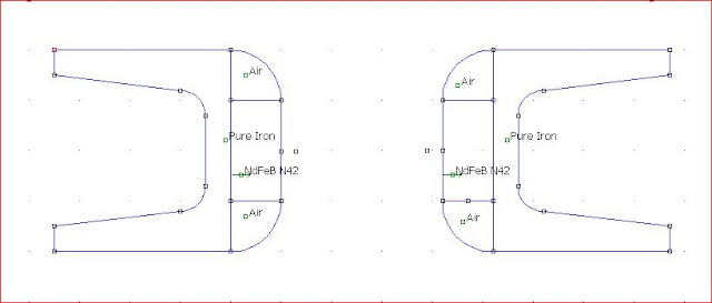
Air gap is 32 mm.
The area noted as air is actually quarter round wood at front and aluminium at the back. The aluminum is hollow and holds the return cables.
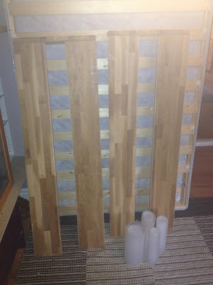
So I should have quarter rounds at the end of the baffle as well:
Then I would end up with 6 cm baffles.
Perhaps I should move the return cables to inside the U.
I think I then have to reset my input criteria.
I have actually tried (and understood) all the things that you mentioned, but obviously ended with the wrong conclusion.
This is what the bare ribbon driver looks like using FEMM:
Air gap is 32 mm.
The area noted as air is actually quarter round wood at front and aluminium at the back. The aluminum is hollow and holds the return cables.
So I should have quarter rounds at the end of the baffle as well:
Then I would end up with 6 cm baffles.
Perhaps I should move the return cables to inside the U.
Yes, I saw your pictures, StigErik.I solved this by using two H-baffle bass towers on each side with the ribbon in the middle. The towers are spaced more than 1 meter from each other.
I don't have that kind of large room that you have.
I have to cope with 3,2 x 5,0 m.
I don't "want" H-baffles, for the bass, I'm aiming at OBs.
But if I don't need to isolate the bass drivers from the ribbon drivers it will be a much easier task to experiment with the bass baffles.
I just make a broad enough baffle to hold the bass drivers and then just add on whatever extensions I like.
Last edited:
I still like them, the reason for buying and using them though was to be able to play music loud at 2 in the night not disturbing my neighbours...
What do you not like about the K340?
..
I have tried fairly narrow flat baffles for woofers. Didnt work all to well because of too much dipole cancellation and resulting distortion. I found out you must have large path length to get good bass, and that means H-baffles or extremely wide flat baffles....
I will recommend placing the dipole peak of the woofer baffles at or just below the crossover frequency.
I will recommend placing the dipole peak of the woofer baffles at or just below the crossover frequency.
I got a suggestion to place the side baffles at an angle somewhere between 90 degrees (H-frame) and 0 degress (OB).
Then perhaps letting one point forward and one backward.
One could even have them in a X shape (from above that is) and thus have the foot print more forward/backward than left/right.
Having all these four baffles foldable would also allow you to experiment and also the woofer can be tucked away when not listening.
Some quick ASCII art:
Actually, this was my setup a couple of years when I had my old subs:
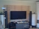
So removing the kitchen drawer mat:
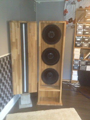
and removing the ribbon baffles:
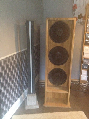
continuing with switching woofers and ribbons and adding the quarter round wood:
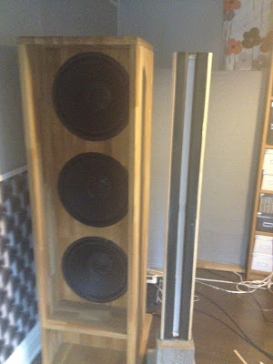
resulted in this new old setup:
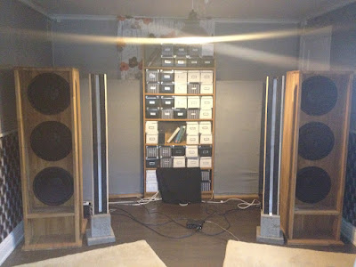
R.I.P.:
So now I'm ready for my new OB woofers...
So removing the kitchen drawer mat:
and removing the ribbon baffles:
continuing with switching woofers and ribbons and adding the quarter round wood:
resulted in this new old setup:
R.I.P.:
So now I'm ready for my new OB woofers...
Yes, I saw your pictures, StigErik.
I don't have that kind of large room that you have.
I have to cope with 3,2 x 5,0 m.
Well ... in my opinion, near-field listening is never a bad idea, and much less so if the room is small.
Someone needs to talk about the Elephant in the room.
In your small room, your speakers are as big as an elephant.
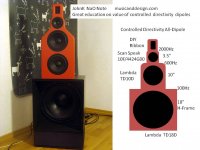
From what I have learned, your IMG_022 arrangement with the narrow baffle ribbon on the inside sound stage has the potential for great sound. Dipoles sound best when they are 4' or more away from every wall, and in your small room the H-frame is right next to the side wall. Personally, I would experiment with minor changes to IMG_022 and understand that the small room will limit its full potential.
I continue to learn from JohnK's work on controlled directivity dipoles like the NaO NOTE. musicanddesign.com A review might generate some interest in his research and possible construction of a smaller 4-way dipole that is better size matched to your room. You could DIY a wide ribbon dipole tweeter. JohnK just finished a new narrower NOTE bass frame. In the USA, the AE Lambda TD10D dipole midbass and TD18D dipole woofer are speaker porn. I use old Lambda TD15D dipole woofers.
Most NdFeB ribbons use a simple construction where the magnets are next to the ribbon on the inside of the pole steel, and several thin rear steel cross supports are added for strength and to close the magnetic circuit to increase the gap flux. A FEMM simulation quickly shows where stray magetic fields between the rear steel bracing can cancel a portion of the gap magnetic field.
In your small room, your speakers are as big as an elephant.
From what I have learned, your IMG_022 arrangement with the narrow baffle ribbon on the inside sound stage has the potential for great sound. Dipoles sound best when they are 4' or more away from every wall, and in your small room the H-frame is right next to the side wall. Personally, I would experiment with minor changes to IMG_022 and understand that the small room will limit its full potential.
I continue to learn from JohnK's work on controlled directivity dipoles like the NaO NOTE. musicanddesign.com A review might generate some interest in his research and possible construction of a smaller 4-way dipole that is better size matched to your room. You could DIY a wide ribbon dipole tweeter. JohnK just finished a new narrower NOTE bass frame. In the USA, the AE Lambda TD10D dipole midbass and TD18D dipole woofer are speaker porn. I use old Lambda TD15D dipole woofers.
Most NdFeB ribbons use a simple construction where the magnets are next to the ribbon on the inside of the pole steel, and several thin rear steel cross supports are added for strength and to close the magnetic circuit to increase the gap flux. A FEMM simulation quickly shows where stray magetic fields between the rear steel bracing can cancel a portion of the gap magnetic field.
Attachments

Last edited:
I'm very well aware of the elephant but it is an elephant by choice.
In fact, the room layout isn´t a straight 3x5 m rectangle.
On the left side of the left speaker there's a door opening into another room and on the right side of the right speaker there´s a garret, 1,2 meters wide and 70 cm deep.
I guess they both widens the room for the dipole woofers.
But sure, it could never hurt to move the away from the wall a couple of inches.
In the left picture you suggest to move the ribbon speaker close to the woofer baffle. Could you please explain why? (Doing it is not that simple as the previous changes).
I see that the ribbons are not flush to the woofer, my mistake. I have already a 0,73 ms delay for the ribbon speakers to correct for a flush mount.
Very interesting setup in the middle picture.
But AE elements are even harder to come by in Sweden. And then there´s the shipping cost and toll and taxes to pay so the total cost is nearly the double.
The modified DAC I currently have only supports 2x2 24/96 outputs and as I kind of like the USB way of solving the PC to amplifier problem I just wait until there´s some USB 3.0 DACs with more 24/96 outputs so I can still use XO and PEQ in the digital domain for all element´s amplifiers.
Also the tweeter would need some kind of transformer I reckon and it is not (currently) my domain.
All in all, I think I stick with my simpler setup for a while though.
I don't understand your last paragraph.
Do you mean that I should close the circuit or not? If you can elaborate on that I would be pleased.
When I simulated a closure of the magnetic circuit in FEMM it didn't give much due to the saturation anyway.
My concern was that little was gained compared to that it wouldn't be a true dipole any more.
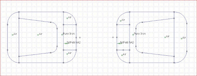
Looking at the driver again, top view:
The ribbon is between the two middle dots.
A flux density plot:
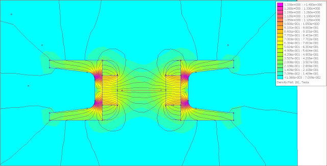
The flux is uniform in vertical plane for practical ribbon excursions but not in horisontal plane (x):
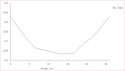
I have solved by using the method with different widths of the aluminium strips giving different current density; wider at the ends where the flux is stronger and narrower in the middle when the flux is smaller.
So Bxi is somewhat linear over the gap giving the same resulting force over the ribbon's surface. But I guess you already know all this.
In fact, the room layout isn´t a straight 3x5 m rectangle.
On the left side of the left speaker there's a door opening into another room and on the right side of the right speaker there´s a garret, 1,2 meters wide and 70 cm deep.
I guess they both widens the room for the dipole woofers.
But sure, it could never hurt to move the away from the wall a couple of inches.
In the left picture you suggest to move the ribbon speaker close to the woofer baffle. Could you please explain why? (Doing it is not that simple as the previous changes).
I see that the ribbons are not flush to the woofer, my mistake. I have already a 0,73 ms delay for the ribbon speakers to correct for a flush mount.
Very interesting setup in the middle picture.
But AE elements are even harder to come by in Sweden. And then there´s the shipping cost and toll and taxes to pay so the total cost is nearly the double.
The modified DAC I currently have only supports 2x2 24/96 outputs and as I kind of like the USB way of solving the PC to amplifier problem I just wait until there´s some USB 3.0 DACs with more 24/96 outputs so I can still use XO and PEQ in the digital domain for all element´s amplifiers.
Also the tweeter would need some kind of transformer I reckon and it is not (currently) my domain.
All in all, I think I stick with my simpler setup for a while though.
I don't understand your last paragraph.
Do you mean that I should close the circuit or not? If you can elaborate on that I would be pleased.
When I simulated a closure of the magnetic circuit in FEMM it didn't give much due to the saturation anyway.
My concern was that little was gained compared to that it wouldn't be a true dipole any more.
Looking at the driver again, top view:
The ribbon is between the two middle dots.
A flux density plot:
The flux is uniform in vertical plane
for practical ribbon excursions but not in horisontal plane (x):
I have solved by using the method with different widths of the aluminium strips giving different current density; wider at the ends where the flux is stronger and narrower in the middle when the flux is smaller.
So Bxi is somewhat linear over the gap giving the same resulting force over the ribbon's surface. But I guess you already know all this.
- Status
- This old topic is closed. If you want to reopen this topic, contact a moderator using the "Report Post" button.
- Home
- Loudspeakers
- Planars & Exotics
- Baffle surface for a long ribbon