
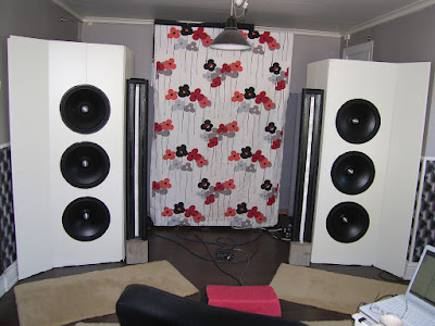
"In the left picture IMG_022 you suggest to move the ribbon speaker close to the woofer baffle. Could you please explain why? "
1) To minimize lobing, I always attempt to keep the driver physical separation below a quarter crossover wavelength, which is 17" C-C for 200Hz. 2) The ribbon-woofer gap will create some additional local dipole cancellation around the ribbon baffle at certain frequencies. This should show up in measurements as a dip around 3Khz, the wavelength width of the ribbon baffle. It should be easy to fill this gap as an experiment.
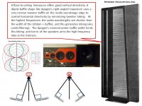
A floor-to-ceiling linesource offers good vertical directivity. A dipole baffle shape like Apogee's right-angled trapezium uses a very narrow tweeter baffle on the inside soundstage edge to control horizontal directivity by minimizing tweeter lobing. At the highest frequencies the audio wavelengths are shorter than the width of the (ribbon + baffle), and this generates lobing (aka comb filtering) The Apogee's minimal center-tweeter baffle width limits this lobing. and toe-in of the speakers aims the high frequency lobe at the listeners. Stig and JohnK discuss using minimal tweeter baffle widths to optimize the high frequency imaging for controlled directivity. NaO NOTE sideways.
"When I simulated a closure of the magnetic circuit in FEMM it didn't give much due to the saturation anyway."
Using only aluminum crossbars will create the most uniform magnetic field. My measurements show about a 10% increase in gap magnetic field when a few thin steel squares are spaced along the rear pole steel. There are DIY ribbons that use very large, thick, steel pole rectangles with thick steel crossbars in order to get about 40% increase in gap field strength. I do not favor this due to cavity resonances and weight.
1) To minimize lobing, I always attempt to keep the driver physical separation below a quarter crossover wavelength, which is 17" C-C for 200Hz. 2) The ribbon-woofer gap will create some additional local dipole cancellation around the ribbon baffle at certain frequencies. This should show up in measurements as a dip around 3Khz, the wavelength width of the ribbon baffle. It should be easy to fill this gap as an experiment.
A floor-to-ceiling linesource offers good vertical directivity. A dipole baffle shape like Apogee's right-angled trapezium uses a very narrow tweeter baffle on the inside soundstage edge to control horizontal directivity by minimizing tweeter lobing. At the highest frequencies the audio wavelengths are shorter than the width of the (ribbon + baffle), and this generates lobing (aka comb filtering) The Apogee's minimal center-tweeter baffle width limits this lobing. and toe-in of the speakers aims the high frequency lobe at the listeners. Stig and JohnK discuss using minimal tweeter baffle widths to optimize the high frequency imaging for controlled directivity. NaO NOTE sideways.
"When I simulated a closure of the magnetic circuit in FEMM it didn't give much due to the saturation anyway."
Using only aluminum crossbars will create the most uniform magnetic field. My measurements show about a 10% increase in gap magnetic field when a few thin steel squares are spaced along the rear pole steel. There are DIY ribbons that use very large, thick, steel pole rectangles with thick steel crossbars in order to get about 40% increase in gap field strength. I do not favor this due to cavity resonances and weight.
Attachments
Separation: I just keep on trying the HolmImpulse-Frequency Allocator loop. And of course listen. As StigErik said, it good to have the two baffles separated so that their toe ins can be varied. I will re-invest in pipe isolation and cut it in halves, to close the gap to a minimum without having woofer vibrations influencing the ribbon baffel.
Magnetic circuit: It was around 10 % increase with sparse rear pole pieces I got as well. I agree that using large and thick pole iron in order to maintain the field will create cavity resonance. In both cases, I didn't bother to implement.
Regarding using steel: Iron is easily obtainable. I haven't looked for martensitic steel in those dimensions. It will be hard work to replace the iron but just out of curiosity, is martensitic "better".
Regarding using steel: Iron is easily obtainable. I haven't looked for martensitic steel in those dimensions. It will be hard work to replace the iron but just out of curiosity, is martensitic "better".
You are correct that "pure iron" is superior to low carbon steel for magnetic circuits. In the USA it is easy to purchase alloy 1008 steel rectangles with tight tolerances and smooth surfaces that do not require machining for pole pieces.
In the USA "ductile iron" is supplied in rectangles with a rough surface. Ductile iron is a lower cost construction material with a loose alloy percentages spec.
I agree that it is better to have a separate baffle for the woofers and mid-tweet as this allows tweeter toe-in and woofer toe-out experiments.
In most comparisons, "pure iron" has a higher saturation polarization(max Tesla) than carbon steel for magnetic circuits, but there are many different grades and so it is difficult to say that all iron material are superior to all steel alloys.
A 3db-5db improvement in SPL/watt sensitivity is very large. You may need to change your magnets, motor topology, ribbon material, and ribbon construction.
If you post a diagram of your ribbon motor design, and info on magnets and ribbon construction the diyAudio brain trust might come up with a few good suggestions. You can decide if the knowledge will contribute to this thread.
Will do , I have gone over the pro and con and have settled on magnets layout and diaphragms, I'm now at Mag/field strength and have a feeling my layout could be better ..
I will post up pics and mag info in a new thread ....
This will be fun (I have a second set of Neo that I can play around with).
Could you share the FEMM-files as well?
Do you have the properties of these materials so I can run FEMM with them?This is very pure iron "Armco Telar 57s".Probably difficult to find and expensive.
I have used some called "Armco" If I remember correctly it costed 10 euro kg.
I simulated using "pure iron" in FEMM and then just bought whatever the shop had in that dimension. I'd like to find out if I have made the totally wrong design decision or if the properties is minor importance in my design.

http://www.flierdl.de/hcrs/Reineisendaten.pdf
looking for where I bought it in Germany. they sold for blacksmiths
looking for where I bought it in Germany. they sold for blacksmiths
Will that be more or less the same as Alloy 1006, which I found in the FEMM material library?In the USA it is easy to purchase alloy 1008 steel .
Will that be more or less the same as Alloy 1006, which I found in the FEMM material library?
I doubt you would see any simulation differences between using Alloy 1006 vs. Alloy 1008 models.
Steel Alloy 1008 has 0.08% carbon.
Steel Alloy 1006 has 0.06% carbon and hence has very slightly superior magnetic properties than Alloy 1008.
In the USA Alloy 1002 rectangles (0.02% carbon) can be found at a few vendors and is a good choice for ribbon pole material if you can find the right size at a price similar to Alloy 1008.
A366/1008 Steel
This alloy is generally used for "commercial quality" cold rolled steel sheet. It is known for its very good formability
and comparatively high strength. It has a very good surface finish that is far superior to hot rolled A36.
ASTM A366 (alloy 1008) steel
Ultimate Tensile Strength, psi 43,900 - 51,900
Yield Strength, psi 26,100 - 34,800
Minimum Properties
Elongation 42 - 48%
Iron (Fe) 99%
Carbon (C) 0.08%
Manganese (Mn) 0.6% max
Phosphorus (P) 0.035% max
Copper (Cu) 0.2% min
Chemistry
Sulfur (S) 0.04%
Last edited:
I tried different alloys as material in FEMM with very little difference in the gap´s flux, even compared to "pure iron".
If you don't close the loop I'd say that the steel´s quality is of little significance.
It is its mechanical strength and its ability to concentrate the flux density in the gap that matters.
Using no iron at at all gives at a given y-interval (+/- 2 mm) 0,252 to 0,26 compared with "pure iron" 0,345 to 0.355 Tesla. It´s about the same differences in x-direction (that is pole to pole).
Upping the magnetic force could be one way of increasing the sensitivity either by using more magnets or by using better Neos. Going from N35 to N42 gives a 10 % increase.
Another way is to corrugate the foil or look at the driver´s geometry. One also then has to think about the compression, it is good if the difference in y-direction is more or less the same over the intended "Xmax" (+/- 2 mm ?)
@a.wayne: Seems that we´re waiting for your promised thread. Right now this thread got a little OT.
..
In the USA, the AE Lambda TD10D dipole midbass and TD18D dipole woofer are speaker porn. I use old Lambda TD15D dipole woofers.
..
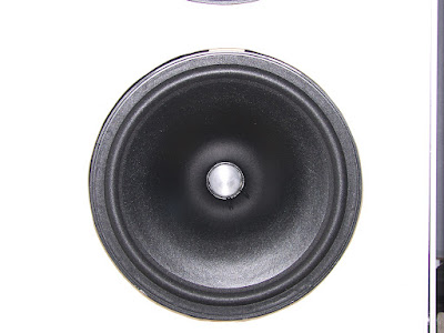
So I thought I´d use some TD15H Apollo for my new woofers.
This is how it turned out:
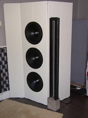
Close up:
Yet another close up:
There´s a thread in the sub-woofer section that shows how it was done.
- Status
- This old topic is closed. If you want to reopen this topic, contact a moderator using the "Report Post" button.
- Home
- Loudspeakers
- Planars & Exotics
- Baffle surface for a long ribbon