For a few weeks now (since it got into the low 50s inside at night due to heater malfunction - hint!) I have had one panel drop in output level intermittently. Never off, just drops (or fades, depending on how loudly it's playing) down 'a step' it seems, as image center is then fixed and stays at about half-way over to the other side when this happens. After minutes or seconds a bass thump can put it back to centered. A whack with a rubber mallet can also fix it temporarily, and it can also come back without any apparent vibrations. And when it comes back it fades back (like the ~1 second it takes to recharge when they first come on), not pops or snaps back.
My audiophilia nervosa immediately caused me to think I had broken the connection to the diaphragm at the panel (due to my laziness of correcting the panel slip that ML designed in), but I swapped the panels, and the problem stayed with the box fortunately. (Although I quickly mounted the 'anti-slip clips' that ML sent - which are completely useless without adding a spacer btw...)
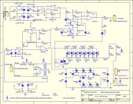
I have reasoned down these symptoms into believing there's something flaky in the cap-diode ladder: flaky (self-healing?) 0.1uF 630V cap, cold solder joint, broken/leaking pcb trace, etc. (but NOT one of the mega ohm resistors R21-25, since the faulty lower level stays fixed).
As much as I'd like to be systematic about diagnosing this and seeing a 'smoking gun' in there, I would rather be practical and just fix it once and for all and on both sides. (I don't want to open these up more often than necessary.) Plus I'm considering adding more caps and diodes to the HV ladder where ML has left space on the pcb, as I will sooner than later go active and use smaller amplifiers for the ESL (so I could use the extra HV, right? What's one more rung on the ladder going to hurt?!). So now I would just buy enough new caps and diodes (9 per side rather than 8), put them in and hear what happens.
Is my reasoning good, and is this a good plan?
My audiophilia nervosa immediately caused me to think I had broken the connection to the diaphragm at the panel (due to my laziness of correcting the panel slip that ML designed in), but I swapped the panels, and the problem stayed with the box fortunately. (Although I quickly mounted the 'anti-slip clips' that ML sent - which are completely useless without adding a spacer btw...)
I have reasoned down these symptoms into believing there's something flaky in the cap-diode ladder: flaky (self-healing?) 0.1uF 630V cap, cold solder joint, broken/leaking pcb trace, etc. (but NOT one of the mega ohm resistors R21-25, since the faulty lower level stays fixed).
As much as I'd like to be systematic about diagnosing this and seeing a 'smoking gun' in there, I would rather be practical and just fix it once and for all and on both sides. (I don't want to open these up more often than necessary.) Plus I'm considering adding more caps and diodes to the HV ladder where ML has left space on the pcb, as I will sooner than later go active and use smaller amplifiers for the ESL (so I could use the extra HV, right? What's one more rung on the ladder going to hurt?!). So now I would just buy enough new caps and diodes (9 per side rather than 8), put them in and hear what happens.
Is my reasoning good, and is this a good plan?
Attachments
For a few weeks now (since it got into the low 50s inside at night due to heater malfunction - hint!) I have had one panel drop in output level intermittently. Never off, just drops (or fades, depending on how loudly it's playing) down 'a step' it seems, as image center is then fixed and stays at about half-way over to the other side when this happens. After minutes or seconds a bass thump can put it back to centered. A whack with a rubber mallet can also fix it temporarily, and it can also come back without any apparent vibrations. And when it comes back it fades back (like the ~1 second it takes to recharge when they first come on), not pops or snaps back.
I have reasoned down these symptoms into believing there's something flaky in the cap-diode ladder: flaky (self-healing?) 0.1uF 630V cap, cold solder joint, broken/leaking pcb trace, etc. (but NOT one of the mega ohm resistors R21-25, since the faulty lower level stays fixed).
Ugh. Intermittent problems are always a pain to diagnose, and always leave you wondering if you really have it fixed. Based on your description of the symptoms, your diagnosis certainly sounds plausible to me. You didn’t mention it, but I’m assuming the auto ON/OFF power LED stays on the whole time, right?
Is it possible to operate the speakers with the HV power supply board exposed?
I would recommend measuring the AC voltage at the input of the multiplier chain when the ESL has dropped in level. You should be able to do this with a standard DVM. If the AC voltage hasn’t dropped in level, you have confirmed the problem is in the multiplier.
If it does drop in level, it is not the multiplier and you need to look further upstream. Note that ML uses zener diodes (Z3-Z13) to regulate the peak amplitude of the AC voltage reaching the multiplier. If one of the 1N4756A was intermittently shorting out, this would drop the level of the voltage reaching the multiplier by a step like you describe.
Last edited:
Bolserst, thanks for helping!
There is a sprayed-on conformal coating, so I will scratch that off to make connections. Does this coating need to be repaired once I'm done?
My meter will measure up to 1000VDC (and 750VAC), so would checking the HV across an individual cap or diode in the ladder narrow down the problem?
And any comments on my future plans to add another cap and diode to step up the HV?
Correct.You didn’t mention it, but I’m assuming the auto ON/OFF power LED stays on the whole time, right?
Yes, I should be able to measure the AC voltage at the input to the multiplier ladder, and I will try that next.Is it possible to operate the speakers with the HV power supply board exposed?
I would recommend measuring the AC voltage at the input of the multiplier chain when the ESL has dropped in level. You should be able to do this with a standard DVM. If the AC voltage hasn’t dropped in level, you have confirmed the problem is in the multiplier.
If it does drop in level, it is not the multiplier and you need to look further upstream. Note that ML uses zener diodes (Z3-Z13) to regulate the peak amplitude of the AC voltage reaching the multiplier. If one of the 1N4756A was intermittently shorting out, this would drop the level of the voltage reaching the multiplier by a step like you describe.
There is a sprayed-on conformal coating, so I will scratch that off to make connections. Does this coating need to be repaired once I'm done?
My meter will measure up to 1000VDC (and 750VAC), so would checking the HV across an individual cap or diode in the ladder narrow down the problem?
And any comments on my future plans to add another cap and diode to step up the HV?
There is a sprayed-on conformal coating, so I will scratch that off to make connections. Does this coating need to be repaired once I'm done?
The SL3 doesn't use particularly HV, so I personally wouldn't worry about re-coating unless you happen to live right on the coast and the air is particularly salty.
Most DVMs have an input impedance of about 10Mohm. This input impedance will be too low to accurately read the DC voltage across each individual cap without significantly discharging it in the process. The discharging issue will get worse as you measure the caps further along the multiplier. You would need to build, buy, or borrow a HV probe to use with your DVM which has an input impedance on the order 1000Mohm. That being said, if you do determine the multiplier is the problem, you might be able to figure out which cap/diode pair is at fault with your DVM even with the discharge issue.My meter will measure up to 1000VDC (and 750VAC), so would checking the HV across an individual cap or diode in the ladder narrow down the problem?
A cheap and easy way to get a little more output with the lower power amps you mentioned. I'd say give it a try. If the diaphragms collapse to the rear stator, or you experience ticking/buzzing noises, just bump it back down to stock level. Your success will depend on the cleanliness of the panels and the tension on the diaphragms.And any comments on my future plans to add another cap and diode to step up the HV?
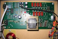
I took out the pcb and had a close look at it, but nothing looked 'wrong,' so I put it back and connected the meter to the anode of D13 (output of transformer) and the anode of D12 (ground) to measure the AC at the input to the multiplier, as you suggested, bolserst.
And the readings were all over the place, so bad I thought my Fluke 73 meter was faulty (or can't read it as true AC?). Anything from 1.5VAC to 261VAC! When the sound output was at max, it seemed steady at 261VAC, and that's the highest I observed. But a knock on the panel will send the reading fluctuating....
So that means a goofy zener diode?
I took out the pcb and had a close look at it, but nothing looked 'wrong,' so I put it back and connected the meter to the anode of D13 (output of transformer) and the anode of D12 (ground) to measure the AC at the input to the multiplier,
When the sound output was at max, it seemed steady at 261VAC, and that's the highest I observed. But a knock on the panel will send the reading fluctuating....
So that means a goofy zener diode?
It's tough to say conclusively based just on this voltage measurement, but that is a good start. Obviously a component shunted across the supply is intermittently shorting, or a component (or solder joint) in series with the supply is intermittently going open circuit.
Since you seem to be able to knock the supply between states of working properly and improperly, I'd recommend checking the series dropper resistors R23 & R24 next. Measure the AC voltage across each one independently when the supply is working properly, and when it isn't. It is highly unlikely that both R23 & R24 are failing at the same time, so if they both give similar readings to each other in both states, then they are not the culprit, and we can move on to the shunt caps and diodes. If one has a much higher voltage across it when the supply is working improperly, then it is failing open. Since these resistors get hot, you might also take a closer look at their solder joints to make sure they are in good shape.
Measuring the voltage drop across R23 & R24 will also allow you to calculate what the voltage output of the transformer would be if the zener diode chain was removed momentarily for troubleshooting purposes. But, lets see what the results of the R23/R24 tests are first.
Bolserst, thank you for walking me through this! I had not expected to learn all these nuances about my HV supply.
Voltage drop across both R23 and R24 (1.8k 3W -- mildly warm) varies between 14.7 and 18.4 VAC (but is the same across each one at any given time) depending on the AC voltage measured at the transformer output. At 'full' trafo output (259-261VAC max observed so far), R23 and R24 both have 18.4VAC each.
Voltage drop across both R23 and R24 (1.8k 3W -- mildly warm) varies between 14.7 and 18.4 VAC (but is the same across each one at any given time) depending on the AC voltage measured at the transformer output. At 'full' trafo output (259-261VAC max observed so far), R23 and R24 both have 18.4VAC each.
Short version: The HV secondary in the transformer finally went completely open circuit (while I was tapping on it!), so while I shop for another trafo, I'm supplying the non-working speaker with 260VAC from the trafo output of the working supply, and both speakers are working fine.
Last edited:
Longer version: With bolserst's guidance I checked the following:
-Mains input voltage (swapped AC outlets L to R)
-Bypassed the triac
-Measured voltage at LV secondary: steady 10.8V 'on' and 11.4V 'off'
-Measured caps in HV multiplier: all were 0.1uF
-Checked basic forward/reverse continuity of all diodes
-Disconnected the zener diode string by cutting jumper Z8
As I was checking and tapping, it seemed the speaker was not returning to full output as readily, and then eventually the HV secondary winding failed.
I will report back on my luck in finding a suitable replacement transformer....
ML sold me a transformer for $16+$12 shipping, so that was easy. But I only got around to actually installing it last week!
In the meantime I have been enjoying hearing the uncolored 'dipole' bass resulting from having the rear covers loose (while I was supplying the 260 VAC for both bias supplies from one transformer). Now with the covers back on, of course low bass has returned, but that unboxy bass is something I want to have again in the future...
In the meantime I have been enjoying hearing the uncolored 'dipole' bass resulting from having the rear covers loose (while I was supplying the 260 VAC for both bias supplies from one transformer). Now with the covers back on, of course low bass has returned, but that unboxy bass is something I want to have again in the future...
- Status
- This old topic is closed. If you want to reopen this topic, contact a moderator using the "Report Post" button.
- Home
- Loudspeakers
- Planars & Exotics
- ML SL3 intermittent bias supply problem