Why should I put time and effort into filing the edges on the metal sheets/stators?
The potential will be uniform through each stator and no sparks will jump between edges.
Between the stators there will be non conductive spacers so there should be no problems there either?
Ok, so... I'm a n0ob... sue me.
The potential will be uniform through each stator and no sparks will jump between edges.
Between the stators there will be non conductive spacers so there should be no problems there either?
Ok, so... I'm a n0ob... sue me.
Why should I put time and effort into filing the edges on the metal sheets/stators?
The potential will be uniform through each stator and no sparks will jump between edges.
Between the stators there will be non conductive spacers so there should be no problems there either?
Ok, so... I'm a n0ob... sue me.
I'm no expert, but I suspect the paragraph below, quoted from a Wikapedia article on coronal discharge, is likely correct:
"Corona discharge usually forms at highly curved regions on electrodes, such as sharp corners, projecting points, edges of metal surfaces, or small diameter wires. The high curvature causes a high potential gradient at these locations, so that the air breaks down and forms plasma there first. In order to suppress corona formation, terminals on high voltage equipment are frequently designed with smooth large diameter rounded shapes like balls or toruses."
Here's a link to the full article:
Corona discharge - Wikipedia, the free encyclopedia
Also, I've neglected to mention this embarrassing fact before now, but... when I built my first panels, they played wonderfully for a few seconds, during which time, voltage found and burned through every weak spot along the stator edges... there was audible arcing and the sickening smell of ozone, and while I was diving for the power switch, my old Carver amp sensed the short and shut itself down. When I dismantled the panel to rebuild it, I found burn marks from stator-to-stator arcing at sharper points along the stator edges. The rebuild involved days of toil with paint stripper and a wire brush to get all the paint out of the perf holes. This horrendous experience has made me downright anal about smoothing over sharp edges and insulating the stator edges; which I did on my next panels, using the methods now shown on my website. I haven't had any problems since. Better safe than sorry, I say!
Chaz

CharlieM's analysis is spot on. Sharp edges encourage high potential gradients, corona generation, and eventually arcing. Even if there is no arcing initially, over time ozone generated by the corona promotes surface tracking, attacks the insulation material and causes it to fail.
Here is a pic showing failure of 2 layers of 5mil Kapton tape on the edge of an ESL. With dielectric strength of 3kV/mil, it should have had no problem withstanding the ESL voltages. Failure occurred at several locations adjacent to sharp edges.
http://www.diyaudio.com/forums/planars-exotics/166280-jazzmans-new-stat-panels-5.html#post2820194
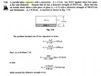
A counterintuitive fact is that inserting insulating material with high dielectric constant in between the stators actually encourages coronal discharge by pushing most of the voltage differential between the stators into the small remaining airgaps between the stators and insulator. This results from increasing the voltage gradient in the air near the stators, rather than reducing it...which was probably the goal of inserting the insulation material. This behavior occurs for both AC and DC voltages. When I first encountered this problem it puzzled me as it seemed the more I tried to insulate the stators the more easily corona formed on them. Taking a step back and thinking about what I was actually doing, and things clicked and started to make sense. See Attachment for a text book numerical example.
Fortunately, the 3M foam tape that most people use for spacing material has a dielectric constant not much higher than air, so this isn't a problem. But, if you decide to use PVC, ABS, or some other plastic as a spacer to separate your perforated metal, you will find corona forming where the stators contact the plastic spacers at significantly lower voltages than it forms anywhere else.
Here is a pic showing failure of 2 layers of 5mil Kapton tape on the edge of an ESL. With dielectric strength of 3kV/mil, it should have had no problem withstanding the ESL voltages. Failure occurred at several locations adjacent to sharp edges.
http://www.diyaudio.com/forums/planars-exotics/166280-jazzmans-new-stat-panels-5.html#post2820194
A counterintuitive fact is that inserting insulating material with high dielectric constant in between the stators actually encourages coronal discharge by pushing most of the voltage differential between the stators into the small remaining airgaps between the stators and insulator. This results from increasing the voltage gradient in the air near the stators, rather than reducing it...which was probably the goal of inserting the insulation material. This behavior occurs for both AC and DC voltages. When I first encountered this problem it puzzled me as it seemed the more I tried to insulate the stators the more easily corona formed on them. Taking a step back and thinking about what I was actually doing, and things clicked and started to make sense. See Attachment for a text book numerical example.
Fortunately, the 3M foam tape that most people use for spacing material has a dielectric constant not much higher than air, so this isn't a problem. But, if you decide to use PVC, ABS, or some other plastic as a spacer to separate your perforated metal, you will find corona forming where the stators contact the plastic spacers at significantly lower voltages than it forms anywhere else.
Attachments
Last edited:
It is funny that you had posted this just after I had got done explaining some of this here,
http://www.diyaudio.com/forums/planars-exotics/203904-another-esl-project.html#post2946775
And here is the after math of what can happen,
http://www.diyaudio.com/forums/planars-exotics/203990-esl-woofer-anybody-game-3.html#post2882069
Because I have been using a wire mesh method for building stators, Sharp edges are a very big deal !!!
My wires are in the order of .009" or 9mil and it is hard enough to get them enough coating thickness in order to not arc.
Here is some of my latest info on this subject,
http://www.diyaudio.com/forums/plan...tric-coatings-fact-fiction-2.html#post2893839
http://www.diyaudio.com/forums/plan...tric-coatings-fact-fiction-2.html#post2894427
http://www.diyaudio.com/forums/plan...tric-coatings-fact-fiction-2.html#post2902754
As you can see in the photos the edges were the hardest part to seal and was where most if not all of my problems would start to occur.
I had the edges buried in clear silicone and it still arced through and that particular point the silicone wasn't thick enough.
On that particular burned panel in the example it took a lot of work and many many tear downs to get the edges sealed properly without any arcs with a 10Kv bias voltage, including taking out all of the silicone and resealing it with some sort of acrylic paints from spray cans and nail polishes.
Let alone the failure that had occurred in the middle of the panel even though it was close to the edge were the actual failure had started in that area to begin with.
This is where carbon depositation may have already set in the material causing a weakness in the coating surface itself.
Also I was pushing for a sustained bias voltage of 10Kv, But that failure occured at about a 5Kv to 7Kv bais voltage and was from nearly 12kv P-P across the stators using test tones at the higher end of the audio spectrum.
Gotta Love R&D !!!
jer
Pardon me for being stupid. (It would be even more stupid to act if I understood though...)
In the pictures of the woofer it looks like the arcing has occured adjacent to the inner edge of the stator distances?
I'm talking of smoothing/rounding the outer edge of the stators where there are some sharp edges from cutting the sheet metal into the right size for the stators.
The outer edge will look like:
Stator | foam tape| uncoated mylar film | foam tape | Stator
I was planning on taping the outer edge with electricians tape as well and it's supposed to be good for up to 10kV?
Any Sharp edges are a bad thing!
The tape is a good thing and will help but if there is any potential for leakages it will arc right around the tape if the voltages are high enough.
I had purposely made my spacer's (the diagphram frame) a little smaller to cover the edges and make a longer path should an arc occur and this worked and this helped many times to keep from burning any holes in the mylar but the arc did go the other way around the frames and arced through a bolt to the other side instead.
jer
Last edited:
![016 [640x480].JPG](/community/data/attachments/264/264929-f7d96c0d89d101775ec701869ce2da3a.jpg)
I've filed down one of my panels, what do you think?
Is it good enough?
It's almost impossible to get the edges perfectly smooth but that looks pretty good to me.
- Status
- This old topic is closed. If you want to reopen this topic, contact a moderator using the "Report Post" button.
- Home
- Loudspeakers
- Planars & Exotics
- Some n0ob ESL questions?