Hello jeronimo83,
Based on your ESL_SEG_UI inputs, the attached schematics show resistor values and wiring connections that would give the calculated response.
If I understand your electrical circuit description correctly, you should use the resistor values in Configuration (4).
Configuration (1) is most directly comparable with the inputs from the program.
Configuration (2) is the symmetric version of (1) where half of the resistance is placed on each stator segment.
Configuration (3) left and right side portion of each segement are connected and driven with one resistor ladder.
Configuration (4) is the symmetric version of (3)
As mentioned previously in this thread, often the resistor for segment 1 is moved to the primary side of the transformer where it can provide core saturation protection as well. In your case with a 150:1 step-up ratio, the 25K resistor could be replaced with a 1 ohm resistor on the primary side of the transformer(resistor "R" in the schematics).
Bolserst, thanks very much for your illustrations. Apparently I made a big mistake. Fortunately, I can make some changes to the circuits that I've soldered quite easily to match configuration nr 1. I will pass the 25k resistor and replace it with a 1 ohm resistor in series with the primary winding of the transformer.
Thanks, again.
Jeroen
(PS sorry for interrupting this thread.)
Bolserst, thanks very much for your illustrations....
(PS sorry for interrupting this thread.)
Glad I could help, and best of luck with your project.
")
This thread was started to share experiences with the ESL_SEG_UI simulator.
So, as WrineX mentioned, your questions were not an interruption at all.
I'm sure other readers will find the discussion useful.
Well I've rebuilt the electrostat with the help of your schematics bolserst and it's working like a charm. Seems to me I've got a nice flat frequency response and a little bit more spread too. Although I do lose a small bit of sound pressure, with the 90 watt amp I've bought recently it's not noticable.
I will now be finishing the subwoofers, which are going to be a dipole M shape. Will keep you posted when things are finished.
I will now be finishing the subwoofers, which are going to be a dipole M shape. Will keep you posted when things are finished.

In response to your question posted here:
http://www.diyaudio.com/forums/plan...tatic-speakers-microphones-5.html#post3539906
Hello jeronimo83,
The measurements showing -9dB at 20kHz are for 12 micron diaphragm alone. When stators are added around the diaphragm things get more complicated. There is now a response boost from the cavity formed between the stators and diaphragm. The exact nature of the boost(frequency and magnitude) will depend on the diaphragm to stator spacing(D/S), stator thicknes, and % open area of the stators. With typical ESL wire stator construction and D/S= 1.5mm - 3mm you can expect about 3dB - 4dB boost in the 10khz - 20kHz range. However, it is best to measure your ESL to find out for sure.
In general, it is recommended to use diaphragm thickness 6 micron or thinner to avoid having to use EQ to compensate for HF roll off. You can't really compensate for this HF roll off with the segmentation resistors since at most they can affect a +3dB/oct slope where as the roll off is a -6dB/oct slope. Also, efficiency would suffer.
However, all is not lost. You can use the resonance between your transformer leakage inductance and ESL capacitance to boost the response to compensate for the HF roll off from diaphragm mass. The center frequency for the boost is fixed by your transformer design, but you can control the magnitude of the boost by varying the resistance in series with the transformer primary. Since you currently have a 1 ohm resistor in series with the primary, you might try changing it to 1/2 ohm to see if you like the sound of the HF balance better. As already mentioned, it is best to measure your ESL to determine what actual response is.
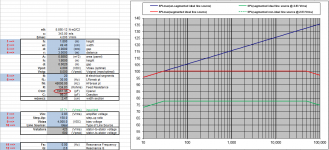
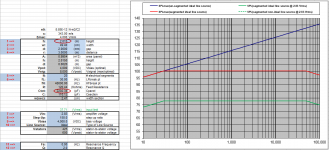
Links to two example trend plots of transformer response with varying resistance in series with primary.
Response for your specific transformer will be different, but damping trends will be similar.
http://www.diyaudio.com/forums/planars-exotics/161485-step-up-transformer-design-20.html#post2147513 (see attachment 3)
http://www.diyaudio.com/forums/planars-exotics/233008-esl-hybrid-2.html#post3441415 (see attachment 2)
What transformer are you using to drive your ESL?
http://www.diyaudio.com/forums/plan...tatic-speakers-microphones-5.html#post3539906
Hi bolserst. Interesting measurements. I've currently made a 12 micron ESL and used the ESL_UI software (which you know well) to calculate segmentation resistors for a flat frequency response. Judging from your measurements, I need to equalize the high frequencies up to almost 9 dB with my diafragm thickness. Am I right? If so, I'd rather use different resistors to compensate for the diafragm roll off.
Hello jeronimo83,
The measurements showing -9dB at 20kHz are for 12 micron diaphragm alone. When stators are added around the diaphragm things get more complicated. There is now a response boost from the cavity formed between the stators and diaphragm. The exact nature of the boost(frequency and magnitude) will depend on the diaphragm to stator spacing(D/S), stator thicknes, and % open area of the stators. With typical ESL wire stator construction and D/S= 1.5mm - 3mm you can expect about 3dB - 4dB boost in the 10khz - 20kHz range. However, it is best to measure your ESL to find out for sure.
In general, it is recommended to use diaphragm thickness 6 micron or thinner to avoid having to use EQ to compensate for HF roll off. You can't really compensate for this HF roll off with the segmentation resistors since at most they can affect a +3dB/oct slope where as the roll off is a -6dB/oct slope. Also, efficiency would suffer.
However, all is not lost. You can use the resonance between your transformer leakage inductance and ESL capacitance to boost the response to compensate for the HF roll off from diaphragm mass. The center frequency for the boost is fixed by your transformer design, but you can control the magnitude of the boost by varying the resistance in series with the transformer primary. Since you currently have a 1 ohm resistor in series with the primary, you might try changing it to 1/2 ohm to see if you like the sound of the HF balance better. As already mentioned, it is best to measure your ESL to determine what actual response is.
Links to two example trend plots of transformer response with varying resistance in series with primary.
Response for your specific transformer will be different, but damping trends will be similar.
http://www.diyaudio.com/forums/planars-exotics/161485-step-up-transformer-design-20.html#post2147513 (see attachment 3)
http://www.diyaudio.com/forums/planars-exotics/233008-esl-hybrid-2.html#post3441415 (see attachment 2)
What transformer are you using to drive your ESL?
In response to your question posted here:
http://www.diyaudio.com/forums/plan...tatic-speakers-microphones-5.html#post3539906
Hello jeronimo83,
The measurements showing -9dB at 20kHz are for 12 micron diaphragm alone. When stators are added around the diaphragm things get more complicated. There is now a response boost from the cavity formed between the stators and diaphragm. The exact nature of the boost(frequency and magnitude) will depend on the diaphragm to stator spacing(D/S), stator thicknes, and % open area of the stators. With typical ESL wire stator construction and D/S= 1.5mm - 3mm you can expect about 3dB - 4dB boost in the 10khz - 20kHz range. However, it is best to measure your ESL to find out for sure.
In general, it is recommended to use diaphragm thickness 6 micron or thinner to avoid having to use EQ to compensate for HF roll off. You can't really compensate for this HF roll off with the segmentation resistors since at most they can affect a +3dB/oct slope where as the roll off is a -6dB/oct slope. Also, efficiency would suffer.
However, all is not lost. You can use the resonance between your transformer leakage inductance and ESL capacitance to boost the response to compensate for the HF roll off from diaphragm mass. The center frequency for the boost is fixed by your transformer design, but you can control the magnitude of the boost by varying the resistance in series with the transformer primary. Since you currently have a 1 ohm resistor in series with the primary, you might try changing it to 1/2 ohm to see if you like the sound of the HF balance better. As already mentioned, it is best to measure your ESL to determine what actual response is.
Links to two example trend plots of transformer response with varying resistance in series with primary.
Response for your specific transformer will be different, but damping trends will be similar.
http://www.diyaudio.com/forums/planars-exotics/161485-step-up-transformer-design-20.html#post2147513 (see attachment 3)
http://www.diyaudio.com/forums/planars-exotics/233008-esl-hybrid-2.html#post3441415 (see attachment 2)
What transformer are you using to drive your ESL?
Thanks for your extensive reply. I realize the thickness of the mylar I used has disadvantages and I might have chosen otherwise. Anyway, this type of mylar was freely available and also had an aluminium layer damped onto it, so I didn't have to fiddle around with membrane coating. Everything is a first in this building project so I tried to minimize the difficulties.
I understand now that I won't be able to get the most out of my project without measuring frequency response when it's finished. I don't have any experience in doing that also and was hoping to avoid it
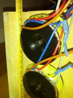
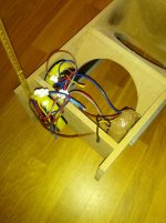
I think I'll keep the 1 ohm resistor in series with the primary in place and see what it does. I have 4x 230v - 6v toroidial transformers per ESL for a total step up of 1:150. I have no exact core dimensions etc. but here are some pictures of the transformers currently attached to the subwoofer cabinet of one of the ESL's.
Attachments
“esl_seg_ui” is a program written by Edo Hulsebos for modeling segmented line source ESLs.
I think you can still download a copy at the following link:
http://www.edohulsebos.nl/apps/esl_seg_ui.part01.exe
Nice to see that my simple program is of use here! I attached the Matlab source code of the program.
Edo
Attachments
Nice to see that my simple program is of use here! I attached the Matlab source code of the program.
Edo
it is verry much so! thank you for all the work!
Thanks for making it available.Nice to see that my simple program is of use here!
It is very handy to have a portable program like this.
You may be interested to know that an English translation of one of your ESL presentations was also posted here on diyAudio.
http://www.diyaudio.com/forums/plan...-esl-project-file-translated.html#post2243663
My apologies...forgot about the other *.rar archive file.
The other part you need is:
http://www.edohulsebos.nl/apps/esl_seg_ui.part02.rar
Place both the *.exe file I linked to in the first post and this *.rar archive in the same folder before running the *.exe self-extracting archive.
I'm hoping someone can tell me what I'm doing wrong (I have Windows 7).
I downloaded both files into a folder and ran the exe. file; which created another folder with a bunch of subfiles but I can't find or open anything that looks like a spreadsheet calculator. Any suggestions?
First you unzip both files part 1&2 into the same folder.
Then you double click on the file that appears to be still zipped, This is a self extracting file and will install the program.
However this program will have either dutch or german dialog but it is very easy to decipher.
There is also a version that was posted in this thread that has been converted to english as well and those files can be found here,
http://www.diyaudio.com/forums/plan...tor-esl-simulator-esl_seg_ui.html#post3192348
These work the same way, You simply unzip all of the files in the same folder and there will be one file that appears to be unzipped after you are done and you execute that file and it will install the program.
It has been a while since I have done this and a possible alternative would be to unzip all but the First file and then just simply execute the first file and it will install the program.
This is only for the english version.
I hope that helps!!
jer
First you unzip both files part 1&2 into the same folder.
Then you double click on the file that appears to be still zipped, This is a self extracting file and will install the program.
However this program will have either dutch or german dialog but it is very easy to decipher.
There is also a version that was posted in this thread that has been converted to english as well and those files can be found here,
http://www.diyaudio.com/forums/plan...tor-esl-simulator-esl_seg_ui.html#post3192348
These work the same way, You simply unzip all of the files in the same folder and there will be one file that appears to be unzipped after you are done and you execute that file and it will install the program.
It has been a while since I have done this and a possible alternative would be to unzip all but the First file and then just simply execute the first file and it will install the program.
This is only for the english version.
I hope that helps!!
jer
I downloaded and unzipped all files, the exe. file (no. 1), followed the prompts to install the files individually, and when the install was done; NOTHING... no spread sheet in the folder or on the desktop or anywhere I look. What did I do wrong?
I downloaded both files into a folder and ran the exe. file; which created another folder with a bunch of subfiles but I can't find or open anything that looks like a spreadsheet calculator. Any suggestions?
The file to run the calculator is a Matlab *.exe file, not a spreadsheet.
I'll grab some step-by-step screenshots during setup of the English version Bazukaz provided in post #39.
Attachment #1: Shows the 7 *.zip files downloaded to a local directory on your computer.
Attachment #2: Shows the result of unzipping the 7 files; 1 *.exe file and 6 *.rar files.
Attachment #3: Double click on the *.exe file to run the extractor. The default directory for the extraction is the current directory.
Attachment #4: After the extractor runs, double click on the "esl_seg_ui" directory
Attachment #5: Locate the "esl_seg_ui.exe" Matlab executable
Attachment #6: After the GUI loads, click the [Simulate ESL] button to calculate response.
Attachments
Hi everyone,
I'm in the process of building a rather large (wide) esl and I made this simulation. I am wondering if wire diameter matters? Or is it only segment surface that matters for simulation? (calculation of total capacity) I'm asking myself this because I use a smaller diameter wire than normally used by DIY-ers (1,1 mm)
Also the wires are extending about 10 cm on both ends of the segment so this would increase the segment capacity a little. I'm wondering if one should measure (check) capacitances of the segments or can I just rely on the calculations of this program?
An externally hosted image should be here but it was not working when we last tested it.
An externally hosted image should be here but it was not working when we last tested it.
It is only the capacitance that matters for segmentation response. The capacitance is calculated using flat plate formula. The spacing between the plates is 2x the D/S spacing. For wire stators D/S = distance from diaphragm to the outer diameter of the wire insulation.… I am wondering if wire diameter matters? Or is it only segment surface that matters for simulation? (calculation of total capacity)
More details on D/S spacing for wire stators here: http://www.diyaudio.com/forums/planars-exotics/281348-sanity-check-wire-stator.html#post4492349
More details on calculating capacitance between stators here: http://www.diyaudio.com/forums/planars-exotics/246846-first-time-esl-builder-12.html#post3881204
This extra extension will increase capacitance of the segments, but will cause only minor changes in response. If you want to try to model with capacitance that more closely represents your actual build, you can do this by adjusting the height to match capacitance. I recommend measuring capacitance of your total panel (ie all segments connected together) rather than individual segments. Then calculate panel height needed to achieve this capacitance for your given stator width and D/S spacing. If you want, you can use the Excel spreadsheet posted here: http://www.diyaudio.com/forums/planars-exotics/48120-experiences-esl-directivity-9.html#post4636649 to do the calculations for you.the wires are extending about 10 cm on both ends of the segment so this would increase the segment capacity a little. I'm wondering if one should measure (check) capacitances of the segments or can I just rely on the calculations of this program
Attachment 1: Entering your panel dimensions into the spreadsheet, you can see that total panel capacitance would be 1967pF.
Attachment 2: Suppose you measure your panel capacitance and it is instead 2200pF. By adjusting the panel height to 2.015m you will match the measured capacitance value. Then, use this 2.015m height value in your esl_seg_ui simulation. If the response changes more than you would like, you can adjust your segmentation resistor values to compensate.
Remember that your diaphragm will have a resonance which will boost the low frequencies. So, you may not need to extend the response so low in frequency with segmentation. Moving the LF roll off point up in frequency will boost the overall sensitivity. The downside to doing this is that the high frequency dispersion will not be quite as good(for the same total panel width). This is an inherent tradeoff with segmentation…sensitivity vs high frequency dispersion. You will need to strike a compromise between an ESL that plays usefully loud and one that has good enough dispersion for a nice sized sweet spot and balanced room ambiance. If you want to keep the same high frequency dispersion you have, but move the LF roll off point up in frequency, you do this by reducing the overall width of the panel.
Attachments
Last edited:
- Status
- This old topic is closed. If you want to reopen this topic, contact a moderator using the "Report Post" button.
- Home
- Loudspeakers
- Planars & Exotics
- Segmented Wire Stator ESL simulator (esl_seg_ui)