I thought I had posted this information before, but when glorocks asked about it in the ESL woofer thread, I couldn't locate it.
Sooooo, I figured it deserved it's own thread.
“esl_seg_ui” is a program written by Edo Hulsenbos for modeling segmented line source ESLs.
I think you can still download a copy at the following link:
http://www.edohulsebos.nl/apps/esl_seg_ui.part01.exe
NOTE:
- See Post#9 for info on additional archive file that is required.
- See Post#39 and Post#75 for English Translation version of esl_seg_ui posted by Bazukaz.
Used with knowledge of its assumptions, I have found the results to be accurate.
The most important assumptions that you need to keep in mind are:
Assumptions
1) ESL panel is assumed to be infinitely tall, or fully filling the floor to ceiling space. If this isn’t the case, keep the listening distance parameter no greater than the height of your ESL panel and the plotted LF results will be reasonably accurate. In practice moving further away than this will result in rolling off of the LF response, but the program does not model this.
- See Post#20 and Post#27 for more details on panel height assumption and LF response.
2) ESL panel width is assumed to be small compared to listening distance. In practice moving closer than about 10x the width of the panel, and the HF response will start to roll off or flatten, but the program does not model this.
3) Audio signal amplitude is assumed to be uniform for all frequencies. So, transform leakage inductance which affects HF bandwidth and peaking/roll-off in the response is not considered.
4) Diaphragm resonance at low frequency is not modeled.
5) It is assumed that there is no capacitive coupling between segments. In practice there is enough coupling that appreciable HF signals are coupled from segment to segment which results in a slightly rising response and poorer off-axis dispersion than the program predicts.
6) No checks are made on the entered voltages to see if they would produce ionization of air in the gap.
7) No checks are made to see if diaphragm would hit stators for entered parameters.
8) The wire spacing and number of wires are used to calculate the width of each segment. This determines the directivity of the segment, and the capacitance which directly influences the acoustic output. It is assumed that the electrostatic field is uniform between the stator wires and diaphragm no matter what the spacing. In general this will be the case if the diaphragm-stator spacing is > openings between wires.
- Some details for estimating efficiency loss with large stator openings can be found here: First time ESL Builder
The simulator was written to model symmetrically segmented ESLs driven either by ladder resistor or parallel resistor networks. Input parameters are entered along the left of the screen. The total number of wires and total width of ESL panel is shown at the bottom left corner. The upper plot shows the NF response of each of the segments. The lower plot shows the summed response at the listening positions for the various off axis angles that have been entered.
Attachment 1: Sample 3 segment ESL output with English labels pasted over the Dutch ones in the GUI screen to help you figure out what the input parameters are.
Attachment 2: Figure showing schematic for the Ladder resistor arrangement.
Attachment 3: Figure showing schematic for the Parallel resistor arrangement.
From the figures you can see that there will actually be 5 segments of wires when building a symmetrical 3 segment ESL.
- See Post#28 for more details on translating the input parameters to electrical layout for building the segmented panel .
Attachments
Last edited:
Thanks,Bolserst, For this thread!
I have been searching for that program as well.
I have been just now contemplating my next panel build and hashing through the power requirements and ratio's of equalizing a panel using a 6db slope filter for five octaves.
So far I have found out that by using this method greatly reduces the power requirements and stresses on the amplifier at the higher frequency's.
Although I have not been able to put this into real world tests until I get some new panels made.
My next little panel will be using some 1/16" TIG rod so that I can try the segmentation method of the stator.
This new panel will be about 50% wider and should result in a little better low end response compared to my last panel.
The horizontal dispersion of my last little panel was at a very respectable -/+ 25 to 30 degrees before any noticeable significant loss of the higher frequency's off of the center axis.
So this will be a very interesting build.
The overall dimensions will be about 11" X 6" for the TIG wire build, and, 12 7/16" X 6" for a new wire mesh panel to compare it to.
The reason for the TIG design to be shorter is due to the size 8" X 10" X .050" thick material that is readily available (home depot).
Also to meet the requirements of fitting on my desktop while increasing the surface area to about 60% more than my original panels.
I still have one panel that should still work to compare the new ones to as well.
All of the panels ave about a 1/2" to 5/8" border.
The diagphram sizes are as follows,
Original 3 1/4" X 9 3/4"
Tig 5" X 10"
New wire mesh 4 5/8 " X 11 1/8"
The D/S has not been determined as of yet but it will be adjustable as with all of my last builds.
The one question that I do have is about the widths of each successive segment.
I have seen two methods have been used in past documentation.
One is with equal widths and another one were each next segment is double the width of the one before it.
I plan on a starting center segment of around 3/8" or 1/2" but I will have the opportunity to change these ratios at will and may even try using every rod as a separate segment too.
I would like too know your opinions on this matter if you would.
Meanwhile, I will start messing with the new program.
Thanks !!!
jer")
I have been searching for that program as well.
I have been just now contemplating my next panel build and hashing through the power requirements and ratio's of equalizing a panel using a 6db slope filter for five octaves.
So far I have found out that by using this method greatly reduces the power requirements and stresses on the amplifier at the higher frequency's.
Although I have not been able to put this into real world tests until I get some new panels made.
My next little panel will be using some 1/16" TIG rod so that I can try the segmentation method of the stator.
This new panel will be about 50% wider and should result in a little better low end response compared to my last panel.
The horizontal dispersion of my last little panel was at a very respectable -/+ 25 to 30 degrees before any noticeable significant loss of the higher frequency's off of the center axis.
So this will be a very interesting build.
The overall dimensions will be about 11" X 6" for the TIG wire build, and, 12 7/16" X 6" for a new wire mesh panel to compare it to.
The reason for the TIG design to be shorter is due to the size 8" X 10" X .050" thick material that is readily available (home depot).
Also to meet the requirements of fitting on my desktop while increasing the surface area to about 60% more than my original panels.
I still have one panel that should still work to compare the new ones to as well.
All of the panels ave about a 1/2" to 5/8" border.
The diagphram sizes are as follows,
Original 3 1/4" X 9 3/4"
Tig 5" X 10"
New wire mesh 4 5/8 " X 11 1/8"
The D/S has not been determined as of yet but it will be adjustable as with all of my last builds.
The one question that I do have is about the widths of each successive segment.
I have seen two methods have been used in past documentation.
One is with equal widths and another one were each next segment is double the width of the one before it.
I plan on a starting center segment of around 3/8" or 1/2" but I will have the opportunity to change these ratios at will and may even try using every rod as a separate segment too.
I would like too know your opinions on this matter if you would.
Meanwhile, I will start messing with the new program.
Thanks !!!
jer
Thank you B!
I have been considering for quite a while building wire stator panels. As I see it, the primary obstacle for most builders is the fabrication of the frames, and more specifically, the wire separators.
I have been in contact with a dude that has a CNC facility, and if we can agree on a few parameters, we could do a group buy.
Once we know the wire type we wish to use and it's diameter, the spacers can be produced on a linear basis. (By the foot)
In this way the construction of the frames may be more easily accomplished by those who don't have access to heavy shop equipment.
Just thinking here---
J
Yes, it is looking for a part 2 file.
But meanwhile in my search for it, I found what looks like a very interesting paper but I believe that it is in german or something and it can be found here,
http://mnierop.home.xs4all.nl/esl_boek_fikier/Hoofdstuk04x.pdf
jer
But meanwhile in my search for it, I found what looks like a very interesting paper but I believe that it is in german or something and it can be found here,
http://mnierop.home.xs4all.nl/esl_boek_fikier/Hoofdstuk04x.pdf
jer
I found it !!!!
here,
Google Translate
jer
P.S. If you are using Google Chrome you just Highlight the link of the missing file part2 and right click search google and the file will down load .
I have the program working !!!! Yeeeeah !!
here,
Google Translate
jer
P.S. If you are using Google Chrome you just Highlight the link of the missing file part2 and right click search google and the file will down load .
I have the program working !!!! Yeeeeah !!
Last edited:
B-
As I recall, there were two parts to this file. Your link only hits one. Ideas?
J-
My apologies...forgot about the other *.rar archive file.
The other part you need is:
http://www.edohulsebos.nl/apps/esl_seg_ui.part02.rar
Place both the *.exe file I linked to in the first post and this *.rar archive in the same folder before running the *.exe self-extracting archive.
Thanks,Bolserst, For this thread!
I have been searching for that program as well.
I have been just now contemplating my next panel build and hashing through the power requirements and ratio's of equalizing a panel using a 6db slope filter for five octaves.
So far I have found out that by using this method greatly reduces the power requirements and stresses on the amplifier at the higher frequency's.
Although I have not been able to put this into real world tests until I get some new panels made.
Hello geraldfryjr,
Glad to hear you got the simulator working...I thought I had posted it back in 2010 when I started the thread on the dutch full range ESL projects.
Oh well, better late than never I guess
http://www.diyaudio.com/forums/plan...-range-dutch-esl-project-file-translated.html
If your panels are closer to square than a line source then the response slope will be 6dB like you mention. In this case, all you need is one resistor in series with the whole panel to flatten the 6dB slope. If you desire to segment to reduce the capacitive load, then you would need to use an inductor ladder network(like Quad ESL63) between segments rather than resistors. Multiple segments driven with ladder resistor networks is mainly useful for flatten the 3dB slope of line sources.
More information on LC transmission line segmentation here:
http://www.diyaudio.com/forums/planars-exotics/192303-curved-vs-flat-esl-panels-3.html#post2680573
The one question that I do have is about the widths of each successive segment.
I have seen two methods have been used in past documentation.
One is with equal widths and another one were each next segment is double the width of the one before it.
I plan on a starting center segment of around 3/8" or 1/2" but I will have the opportunity to change these ratios at will and may even try using every rod as a separate segment too.
I would like too know your opinions on this matter if you would.
Segmentation size is mainly a compromise between ease of build and dispersion. As long as you have at least 3 or 4 segments, you should have no problem finding a combination of segment size and feed resistor values that will provide you a flat response. Personally, I haven't found the use of segments smaller than about 3/4" to improve dispersion because of capacitive coupling between the segments.
Using the simulator you will see that off-axis response changes more smoothly if you keep segment size the same rather than increasing size. You will have to decide how sonically important this is to you.
Thanks,Bolserst,here is what I have came up with so far using the program for my selected panel size.
It has a total of 9 segments like I had wanted to do.
I will look more into increasing the number of segments as I get used to how the program works.
This will be great when I finally get around to finishing the 10" X 36" TIG rod stators that I have already constructed.
Segmenting those will be a breeze with a couple of cut off wheels.
So far this is looking very good and it is very close to to my pink noise measured efficiency of my last little panel even though this design has about 60% more area.
The last panel was at 89.7db with pink noise at no more than 10Vpeak and 87.5db for test tones at 5Vpeak with a 1:256 transformation ratio and 5.56Kv of bias.
I will look more into using inductors as well.
I would think that this would work good for such a smaller panel and might have a better power handling capability than using resistors.
These particular panels will be used in the nearfield mostly but they are the research panels for some 8' line source types to supplement my current woofer system to do away with the dynamic midranges and tweeters in which I keep blowing up any how.
But I can say that my old pair of Pyle PMD5's that I have been using are very good drivers and are the only ones that have survived so far.
Every thing else has gone kaput! He,he,he
The only difference in the two examples is the last resistors in the chain.
The first chart shows a 4.7meg and the second one uses a 10meg for the last resistor.
I will work with it some more but I don't think that I can get it much better than it is the way it is shown.
Thanks again,Cheers !!!
jer
Attachments
Last edited:
WoW,This is Even Better !!!
This is the same as the last post.
Only with just a few resistor tweaks.
I guess the only way to improve the 30 and 45 degree off axis is to use more segments maybe.
jer
P.S Write down your data as there is no save button!
This is the same as the last post.
Only with just a few resistor tweaks.
I guess the only way to improve the 30 and 45 degree off axis is to use more segments maybe.
jer
P.S Write down your data as there is no save button!
Attachments
Last edited:
I don't know how accurate this program is but this shows some incredible results so far.
This is about the best that I can do using 2 rods per section.
There are lots of combinations but that are good.
This one gives me one of the flattest so far within .5db to .75 db.
This is perfect for my requirements right now.
It shows the same results from 60 degrees to 180 degrees as well so this is where I question its accuracy.
But, I will go by these figures and if it does this at over 30 degrees off center than that would be awesome!
I have tried these same setting for some longer panels at 36 inches and the only difference is the values of the resistors are lower.
For this calculation the resistors are as follows for 38 rods per stator,
180k,3.9M,5M,5M,5M,5M,5M,10M,10M,10M.
I used all standard values of resistors as the 5M's will be two 10M's in parallel.
The the only thing I am wondering is how do you determine the wattage of the resistors.
I do plan on doing sweep tests on the panels after they are built and I don't need any failures.
I will try to plot this up in circuit maker and as well as LTSpice as I am just now learning to use that program.
If this works as planned then my planned 6' (2 X 3 foot peices stacked) line source will be perfect for my current system.
Any Suggestions?
jer
Attachments
Last edited:
Ger-
I may be a little off base here, but my reading has told me that inductance may not be a good thing here. I am planning on using non-inductive r's in my build. In the past I have used Caddock metal film resistors, as they are totally non-inductive and dissipate huge amounts of power. You can also heatsink them. What I don't know, is how high a value you gan get. Other drawback is that they can be expensive- I used them in series with the primary of my step-up trafos, and the 25 watt version cost me about 6-8 bucks ea. They come packaged in a TO-220 plastic transistor package. If you subscribe to the notion that you can "hear" resistors, Caddocks get very high marks.
One of the papers from the Dutch ESL club website stated that the builder used 9 watt rated units in his build.
You can also find non-inductive wire-wounds with relative ease at Mouser or Digi-Key.
Again, I may be off base here, but I would resist the temptation to use carbon units. The noise they generate is a function of the applied voltage as I understand it. By the time you get a 9-10 watt rated series parallel network of carbons, you're going to be out several dollars per value anyway and then have to figure out how to neatly package the things.
Jay
I doubt if you could hear it, but I try to cover all the theoretical bases I know about when I build, and don't mind spending a little more on parts if for no other reason than peace of mind.
If you don't have a Mouser catalog, get one. www.mouser.com- free.
Yes, this is understood.
According to ohms laws with a 10kv peak voltage the whole resistor chain of 59.08meg ohms requires a dissipation of only 1.69 watts.
And in the circuitmaker simulation it shows that the 3.9meg ohm resistor requires it to be at least 1.12 watts and the rest are below this value down the chain.
Remember for this simulation this is a very small panel with approximately no more than 2.5pf per section.
So, The current demand is quite small.
This had me quite worried as well as I am well aware of the price of good resistors.
I haven't yet worked out the values of the longer panels as of yet.
But as you know doubling the voltage to 20Kv peak quadruples the power requirement.
But,I highly doubt that I can get my little panel to withstand a 40kv p-p signal and getting it to do 20kv p-p is quite a challange and is where I will set the limit for now. Even half of that at 5kv is sufficient and very loud within 1 meter.
I will show the sims after I study it some more and convert the grahpics to be posted.
Jer
Last edited:
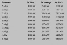
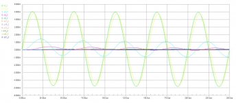
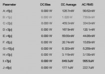
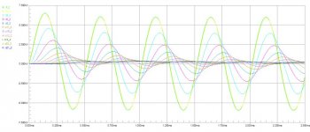
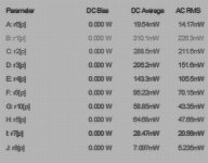
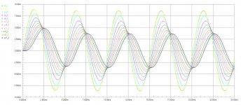
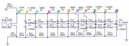
Okay,Here are the circuit maker simulations on my next little panel for resistor power requirements.
Using the example in post #13,
The Diagphram size is 5" X 10" with a D/S at 1.8mm or about .070" (70mil).
This example has 19 separate sections with 2 rods per section and are equally spaced from the center within the 5" width.
The capacitance per section is an estimated 8.368 pf per section and in a real world test this will likely be less than that.
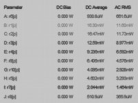
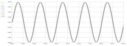
These photos show the test points for voltages on the resistors as well as power dissipation for each of the resistors at 10kv peak and at test frequency's of 20Hz,200hz,2Khz and 20khz.
Cheers !!!

jer
Using the example in post #13,
The Diagphram size is 5" X 10" with a D/S at 1.8mm or about .070" (70mil).
This example has 19 separate sections with 2 rods per section and are equally spaced from the center within the 5" width.
The capacitance per section is an estimated 8.368 pf per section and in a real world test this will likely be less than that.
These photos show the test points for voltages on the resistors as well as power dissipation for each of the resistors at 10kv peak and at test frequency's of 20Hz,200hz,2Khz and 20khz.
Cheers !!!
jer
Attachments
-
 SEGMENTED ESL SIM 20khz resistor power.jpg47.9 KB · Views: 136
 -
 SEGMENTED ESL SIM 20kHz 10Kv.jpg52.3 KB · Views: 145
 -
 SEGMENTED ESL SIM 2khz resistor power.jpg43.5 KB · Views: 146
 -
 SEGMENTED ESL SIM 2kHz 10Kv.jpg57.4 KB · Views: 140
 -
 SEGMENTED ESL SIM 200hz resistor power.jpg109.4 KB · Views: 158
 -
 SEGMENTED ESL SIM 200Hz 10Kv.jpg78.6 KB · Views: 177
 -
 SEGMENTED ESL SIM 20hz resistor power.jpg112.2 KB · Views: 157
 -
 SEGMENTED ESL SIM 20Hz 10Kv.jpg44.7 KB · Views: 230
 -
 test points.jpg66.7 KB · Views: 805
Okay,Here are the circuit maker simulations on my next little panel for resistor power requirements.
Using the example in post #13,
The Diagphram size is 5" X 10" with a D/S at 1.8mm or about .070" (70mil).
This example has 19 separate sections with 2 rods per section and are equally spaced from the center within the 5" width.
The capacitance per section is an estimated 8.368 pf per section and in a real world test this will likely be less than that.
These photos show the test points for voltages on the resistors as well as power dissipation for each of the resistors at 10kv peak and at test frequency's of 20Hz,200hz,2Khz and 20khz.
Cheers !!!
jer
P.S. The capacitance per section was calculated relative the the diagphram so the actual capacitance per section is approximately half (and slightly less) of what was stated.
I don't know how accurate this program is but this shows some incredible results so far.
The program is accurate if used with the calculation assumptions in mind. I'm guessing my description of the assumptions in post#1 is not understood. Also, from looking at your SPICE model, I'm thinking my description of the physical layout the program is modeling based on the input parameters wasn't understood either.
I should have some time later today or tomorrow to post some further clarification on the above two topics.
Your idea to use SPICE to model your finished design to determine power ratings for the ladder resistors is a good one. Rather than looking at just specific frequencies, it is best to do a frequency sweep because power dissipation for each ladder resistor peaks at a different frequency.
Also, don't forget to also consider the voltage ratings. In general, most 2W - 3W metal film or metal oxide resistors are rated for 300VAC - 500VAC. If you get enough of them in series to cover your required voltage rating between sections, you are usually covered for the required power dissipation as well.
Yes,only the First 2 or 3 resistors in the chain will have to made up with a few resistors in series to compensate for the voltage coefficient and breakdown factor (working voltage) that resistors have.
All though this depends on a particular configuration.
But the cool thing is that it shows that only a few of them need to have a higher power rating thus reducing unneeded costs.
I will be looking for your clarifications later.
I do understand the differences in the change of the response curve with distance as was mentioned.
As my new wire mesh flat panel will be used in nearfield use on my desktop and the TIG rod version is to test this dispersion technique in the far field for some large line source panels as mentioned.
jer
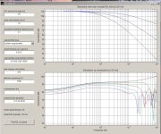
Segmented Wire Stator ESL Simulator (Line Source Assumptions)
The ESL Simulator software assumes that the dimensions and listening distance you enter for modeling describe a Line Source. If they don't, the plotted SPL curves will not predict what you will measure.
An ESL dipole line source by definition has a height that is much larger than the listening distance, and a width that is much smaller than the listening distance. If these two criteria are met, the response will have a slope of 3dB/octave over the whole of the frequency range.
Attachment 1
For example, a 20m high, 0.5cm wide ESL would behave like a line source as modeled.
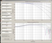
Attachment 2
Change the height to 0.25m, and the sofware still shows the some response since it assumes line source behavior. I reality, a 0.25m x 0.5cm ESL would behave like a point source when viewed from 5m and would have a response sloping off twice as fast, 6dB/oct.
Basically, for line source behavior to be a valid assumption, the listening position must place you in the far-field relative to the width dimension, but in the near-field relative to the height. Some call this the intermediate field.
If the listening position is in the near-field relative to width & height, the response will be flat.
If the listening position is in the far-field relative to width & height, the response will rise at 6dB/oct.
The formula for determining near/far field transition relative to a panel dimension is:
F = c * r / d^2
where:
c = speed of sound
r = listening distance
d = panel dimension
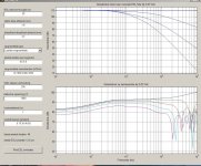
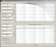
Attachment 3
Here is a plot showing the field transition points for a 0.25m heigh x 12.16cm wide ESL listened to from 1m away. The range of frequencies over which line source behavior is a valid assumption is between the vertical red and yellow dashed lines. To the left of the red line you are in the far-field. So, if the modeling software showed a flat response down to 200 Hz, in reality it would be down -12dB or so.
Attachment 4
Here is a plot showing the field transition points for an ESL similar to an Acoustat. You can see that line source behavior is present down to below 200Hz . With appropriately chosen diaphragm resonance frequency and Q, the 3dB/oct line source slope was extended down to 55Hz or so.
I have attached a zipfile containg the Excel spreadsheet I used to create Attachments 3 & 4.
Perhaps you will find it useful to determine validity of the line source assumptions for the ESL panel you are wanting to model.
The ESL Simulator software assumes that the dimensions and listening distance you enter for modeling describe a Line Source. If they don't, the plotted SPL curves will not predict what you will measure.
An ESL dipole line source by definition has a height that is much larger than the listening distance, and a width that is much smaller than the listening distance. If these two criteria are met, the response will have a slope of 3dB/octave over the whole of the frequency range.
Attachment 1
For example, a 20m high, 0.5cm wide ESL would behave like a line source as modeled.
Attachment 2
Change the height to 0.25m, and the sofware still shows the some response since it assumes line source behavior. I reality, a 0.25m x 0.5cm ESL would behave like a point source when viewed from 5m and would have a response sloping off twice as fast, 6dB/oct.
Basically, for line source behavior to be a valid assumption, the listening position must place you in the far-field relative to the width dimension, but in the near-field relative to the height. Some call this the intermediate field.
If the listening position is in the near-field relative to width & height, the response will be flat.
If the listening position is in the far-field relative to width & height, the response will rise at 6dB/oct.
The formula for determining near/far field transition relative to a panel dimension is:
F = c * r / d^2
where:
c = speed of sound
r = listening distance
d = panel dimension
Attachment 3
Here is a plot showing the field transition points for a 0.25m heigh x 12.16cm wide ESL listened to from 1m away. The range of frequencies over which line source behavior is a valid assumption is between the vertical red and yellow dashed lines. To the left of the red line you are in the far-field. So, if the modeling software showed a flat response down to 200 Hz, in reality it would be down -12dB or so.
Attachment 4
Here is a plot showing the field transition points for an ESL similar to an Acoustat. You can see that line source behavior is present down to below 200Hz . With appropriately chosen diaphragm resonance frequency and Q, the 3dB/oct line source slope was extended down to 55Hz or so.
I have attached a zipfile containg the Excel spreadsheet I used to create Attachments 3 & 4.
Perhaps you will find it useful to determine validity of the line source assumptions for the ESL panel you are wanting to model.
Attachments
Last edited:
- Status
- This old topic is closed. If you want to reopen this topic, contact a moderator using the "Report Post" button.
- Home
- Loudspeakers
- Planars & Exotics
- Segmented Wire Stator ESL simulator (esl_seg_ui)