If you built with 2mm distance between front and rear stator wires, you should enter 1mm for the D/S spacing in the simulation software. This will double the capacitance of the segments. To get the same response you had before you would need to halve the resistor values to: 7.5 40 100 180 800. With only a 1mm D/S spacing, you should also reduce your polarizing voltage from 4kV to 2kV. Unless you plan to only use very low power amplifiers (< 40W), you will likely want to also reduce the transformer test-up ratio from 150:1 to something on the order of 75:1 to 100:1.
The sensitivity(voltage input to SPL output) is increased with the reduced spacing, but the maximum SPL capability at low frequencies will be reduced/limited by the smaller excursion capability.
The sensitivity(voltage input to SPL output) is increased with the reduced spacing, but the maximum SPL capability at low frequencies will be reduced/limited by the smaller excursion capability.
If you built with 2mm distance between front and rear stator wires, you should enter 1mm for the D/S spacing in the simulation software. This will double the capacitance of the segments. To get the same response you had before you would need to halve the resistor values to: 7.5 40 100 180 800. With only a 1mm D/S spacing, you should also reduce your polarizing voltage from 4kV to 2kV. Unless you plan to only use very low power amplifiers (< 40W), you will likely want to also reduce the transformer test-up ratio from 150:1 to something on the order of 75:1 to 100:1.
The sensitivity(voltage input to SPL output) is increased with the reduced spacing, but the maximum SPL capability at low frequencies will be reduced/limited by the smaller excursion capability.
Thanks again for your reply; total distance between front and rear stator (wires) is 4 mm, so D/S spacing is 2mm and that's what I entered into the simulation software. I got a bit confused by this text:
"As long as your chosen D/S is > the gap between the wires, the sensitivity will be essentially the same for all options." (link: http://www.diyaudio.com/forums/planars-exotics/281348-sanity-check-wire-stator.html#post4492349)
In my case both (D/S spacing and gap between the wires) are equal.
Oooooh, I understand what you are asking now....In my case both (D/S spacing and gap between the wires) are equal.
 I will need to re-answer the questions from your previous post.
With gap widths between adjacent wires in the stator equal to the D/S, the measured capacitance of your panel will be about 10% less than for solid stators of the same area. This will result in roughly -1dB less output compared to theory. As mentioned before, you can measure the actual panel capacitance and adjust your inputs to the simulator as needed.… my D/S (2 mm) equals gap width between stator wires (PVC to PVC spacing). I'm wondering if that would affect sensitivity and calculated capacities in the simulation software?
Hello jeronimo83,
As mentioned previously in this thread, often the resistor for segment 1 is moved to the primary side of the transformer where it can provide core saturation protection as well. In your case with a 150:1 step-up ratio, the 25K resistor could be replaced with a 1 ohm resistor on the primary side of the transformer(resistor "R" in the schematics).
OK you guys know I'm the techno-dummy in the class -- and I need a little help understanding how to calculate the change in resistor values if you move the segment 1 resistor to the primary side of the transformer.
I seem to recall reading somewhere (perhaps another post) that the resistor value as reflected through the transformer would be divided (secondary-to-primary) or multiplied (primary to secondary) by the square of the winding ratio? Is that how it works?
Also, I have another question about impedance. Since I don't have the means or smarts to actually measure the impedance of my segmented esl, is it possible to calculate the impedance from the panel configuration and transformer ratio?
thanks,
jazz
Charlie, it's rather simple. Resistance is reflected by the turns' ratio square i.e. (N1/N2)^2.
In case of 1:150 it will be 1:22500 or 1/22500 depending on the side.
Thanks Alexberg, I needed that. Now, one more sanity check-- still not clear on the amount of resistance to reflect. I have no aptitude for math or electronics so please bear with me:
Let's say Im using the version 3 of the Calculator and choosing Symmetric Config 2 with both stators segmented as shown below.
If R=120kOhms and the series resistance feeding section 1 is R/9, then R/9 reflected across the transformer becomes (120000/9)/(76*76) = 2.3 Ohms
Since on the secondary side there is not one but two R/9 resistors (one per stator), I'm confused about whether I need to reflect just R/9 or 2(R/9) or (R/9)/2 to the primary side.
BTW, I'm assuming I should be using version 3 and not version 2 of the Calculator. Note that version 2 shows R/4.5 feeding section 1 and version 3 shows R/9 feeding section 1. Was version 3 a correction?
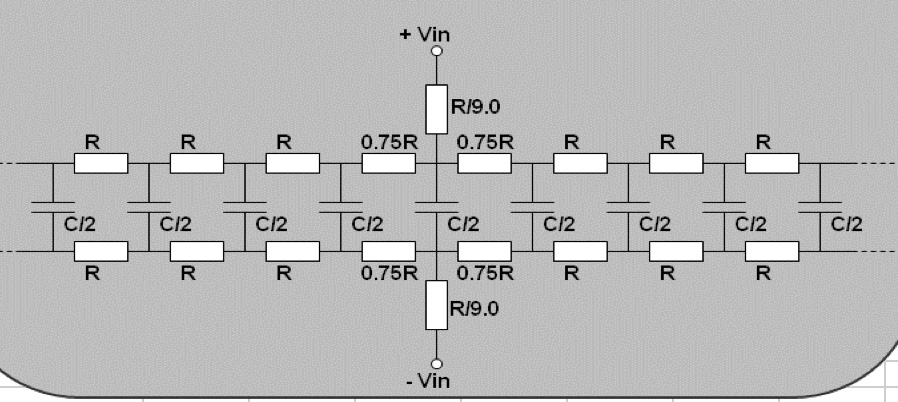
Yes, V3 corrected the lower figure on the Symmetric Config(2) tab of the spreadsheet. Both V2 & V3 have R/4.5 in the upper figure for the single sided segmentation, which is correct. It was only the lower figure that was in error. V2 had R/2.25 in the lower figure when it should be R/9. V3 also added a third figure below it to clarify the relationship between physical and electrical segments. I thought I had mentioned this in the post for V3, but looks like I didn't
Remember, any resistance included in series with the primary will be part of the total resistance feeding the first segment.
If/when there are further revisions/updates, I will add a history tab to the spreadsheet.
http://www.diyaudio.com/forums/planars-exotics/48120-experiences-esl-directivity-9.html#post4636649
Assuming you had a perfect transformer with no losses and no parasitics, your calculation for reflecting R/9 to the primary side is correct. However, you do need to include all impedances element in series, so both R/9 resistors need to be included as well as the impedance of the segment capacitance. In your case, the capacitance is very small < 100pF, so even at high frequencies the combined series impedance reflected to the primary side will be around 15 – 20 ohm at 20kHz and increasing as you go down in frequency.
Basically, with segmented ESLs, the load impedance seen by the amplifier is almost entirely defined by the transformers. The load from the ESL has only a small effect, and only in the top octave. Not sure if you had seen this before, but I had posted a spreadsheet to calculate load impedance for combination of transformers and ESL. You need to know the values for the parasitics of your transformers though. If you are using the Anteks, I could let you know what values to use.
http://www.diyaudio.com/forums/plan...101-electronics-challenged-2.html#post2555863
Yes, V3 corrected the lower figure on the Symmetric Config(2) tab of the spreadsheet. Both V2 & V3 have R/4.5 in the upper figure for the single sided segmentation, which is correct. It was only the lower figure that was in error. V2 had R/2.25 in the lower figure when it should be R/9. V3 also added a third figure below it to clarify the relationship between physical and electrical segments. I thought I had mentioned this in the post for V3, but looks like I didn't
Remember, any resistance included in series with the primary will be part of the total resistance feeding the first segment.
If/when there are further revisions/updates, I will add a history tab to the spreadsheet.
http://www.diyaudio.com/forums/planars-exotics/48120-experiences-esl-directivity-9.html#post4636649
Assuming you had a perfect transformer with no losses and no parasitics, your calculation for reflecting R/9 to the primary side is correct. However, you do need to include all impedances element in series, so both R/9 resistors need to be included as well as the impedance of the segment capacitance. In your case, the capacitance is very small < 100pF, so even at high frequencies the combined series impedance reflected to the primary side will be around 15 – 20 ohm at 20kHz and increasing as you go down in frequency.
Basically, with segmented ESLs, the load impedance seen by the amplifier is almost entirely defined by the transformers. The load from the ESL has only a small effect, and only in the top octave. Not sure if you had seen this before, but I had posted a spreadsheet to calculate load impedance for combination of transformers and ESL. You need to know the values for the parasitics of your transformers though. If you are using the Anteks, I could let you know what values to use.
http://www.diyaudio.com/forums/plan...101-electronics-challenged-2.html#post2555863
Thanks for taking the time to explain that Steve. I take it then that I would need to reflect 2(R/9) to the primary side; which would be 4.6 Ohms excluding the segment impedance you mentioned. 4.6 Ohms seems like a lot but if that's what it takes....
At present my speaker has no resistors on segment 1, 60kOhms in lieu of 90kOhms (.75R) on segment 2, and only 1 Ohm added to on the primary side. The speaker sounds pretty fantastic as-is but maybe I should try to get it right, as it were. I'm so treble deaf I can't be sure what sounds right to others, though.
There is zero probability that I will ever really grasp what's going on with segmentation and transformers, I would just like to explain correctly on my website, in layman's terms, how to build my speaker (I like to think my website is an enabling resource for others like myself with no electronics or math skills).
Last edited:
If you were using ideal transformers, 4.6 ohms is exactly what you would want to use. But when using real transformers with leakage inductance and winding capacitance it is not that simple. Generally, you will need to use a much lower resistance in the 1 - 2 ohm range to properly damp the transformer resonance AND adjust response for the removal of the 2(R/9) resistance from the secondary side....I take it then that I would need to reflect 2(R/9) to the primary side; which would be 4.6 Ohms excluding the segment impedance you mentioned. 4.6 Ohms seems like a lot but if that's what it takes....
Based on a quick simulation of your ESL with Antek transformer parasitics, your setup with 1 ohm looks to be just about spot on. When I get time tomorrow, I will post some response pics and schematics for few different setups with Ideal and Real transformers to help explain what is going on. It should provide the information you are looking for without getting too technical.
Based on various PMs I've received in the past few years, I can definitely say your website has been a valuable resource for many.
BTW, just saw over the weekend you got to show off your speakers a few months ago to none other than Bob Carver!
Very cool indeed
CharlieM & Bob Carver
In the 80-90s I sold Bob Carver Speakers, Amps an all other audio product ....One of great guys in the Audio world... like Mr Pass.... always welling to help others ...never fear there giving any of there Audio magic away.....
thanks for posting the info an pic CharlieM
Vary Cool
thanks for posting the info an pic CharlieM
Vary Cool
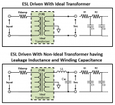
The main difference between ideal and real transformers that affects the high frequency response of ESLs is the presence of leakage inductance and winding capacitance. These non-ideal effects in real transformers result in limitations on the high frequency bandwidth as well as peaking in the response before roll-off.
Attachment #1: Comparison of Ideal and Real transformers driving a segmented ESL. Note the location of the leakage inductance and winding capacitance components in the Real transformer circuit.
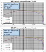
Attachment #2: Modeled response of your ESL with Ideal transformers. Comparison of configurations with R1 on the secondary side and when it is moved to the primary side by setting R1=0 and Rdamp = 4.9. You can see the responses are the same.
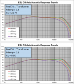
Attachment #3: Modeled response of your ESL with Real Antek transformers. Comparison of configurations with R1 on the secondary side and when it is moved to the primary side…much different than the ideal case. Note the peaking in the upper figure from resonance between the LL and Cw. When Rdamp is increased to 4.9 ohm in the lower figure you now get HF roll off because you have moved the R1 resistance upstream of Cw which is around 1200pF.
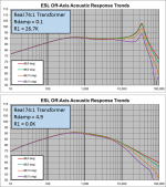
Attachment #4: Modeled response of your ESL with Real Antek transformers. Upper figure shows that if Rdamp is increased to 0.6 ohm the peaking is damped to a response essentially the same as the ideal case below 30kHz. The lower figure shows what happens if you removed the R1 resistance…a rising response in the top 2 octaves.
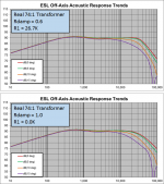
Attachment #4: Modeled response of your ESL with Real Antek transformers. Upper figure is a repeat of from Attachment #3. The lower figure shows that if Rdamp is increased slightly to 1.0 ohm the rising response from removing the R1 resistance is compensated for; this is no where near the 4.9 ohm needed in the ideal transformer case. Note also that HF roll-off starts a little lower now. Again, this is the result of moving some resistance upstream of Cw.
The general guidance for segmented ESLs is that R1 can be removed and Rdamp increased slightly to compensate and flatten the response.
=========================
Link to Antek transformer measurements:
http://www.diyaudio.com/forums/plan...p-up-measurements-part-1-2-a.html#post2823635
- Leakage inductance results from imperfect coupling between the primary and secondary windings.
The effect can be modeled by adding an inductance in series with the output of the secondary from an ideal transformer.
- Winding Capacitance results from the separate layers of the secondary acting like plates of a capacitor.
The effect can be modeled by adding a capacitor across the output of the secondary downstream from the leakage inductance.
Attachment #1: Comparison of Ideal and Real transformers driving a segmented ESL. Note the location of the leakage inductance and winding capacitance components in the Real transformer circuit.
Attachment #2: Modeled response of your ESL with Ideal transformers. Comparison of configurations with R1 on the secondary side and when it is moved to the primary side by setting R1=0 and Rdamp = 4.9. You can see the responses are the same.
Attachment #3: Modeled response of your ESL with Real Antek transformers. Comparison of configurations with R1 on the secondary side and when it is moved to the primary side…much different than the ideal case. Note the peaking in the upper figure from resonance between the LL and Cw. When Rdamp is increased to 4.9 ohm in the lower figure you now get HF roll off because you have moved the R1 resistance upstream of Cw which is around 1200pF.
Attachment #4: Modeled response of your ESL with Real Antek transformers. Upper figure shows that if Rdamp is increased to 0.6 ohm the peaking is damped to a response essentially the same as the ideal case below 30kHz. The lower figure shows what happens if you removed the R1 resistance…a rising response in the top 2 octaves.
Attachment #4: Modeled response of your ESL with Real Antek transformers. Upper figure is a repeat of from Attachment #3. The lower figure shows that if Rdamp is increased slightly to 1.0 ohm the rising response from removing the R1 resistance is compensated for; this is no where near the 4.9 ohm needed in the ideal transformer case. Note also that HF roll-off starts a little lower now. Again, this is the result of moving some resistance upstream of Cw.
The general guidance for segmented ESLs is that R1 can be removed and Rdamp increased slightly to compensate and flatten the response.
=========================
Link to Antek transformer measurements:
http://www.diyaudio.com/forums/plan...p-up-measurements-part-1-2-a.html#post2823635
Attachments
Last edited:
Steve,
Your last post, especially attachments 1 & 3 were eye openers for me. I have confidence now that my speaker is close to optimal as is. And as I recall, I got the tip from you to omit the R1 resistors and keep the 1Ohm on the primary.
I was groping around like a blind man in a brothel when I started the build but thanks to you and Golfnut, I have an amazing speaker!
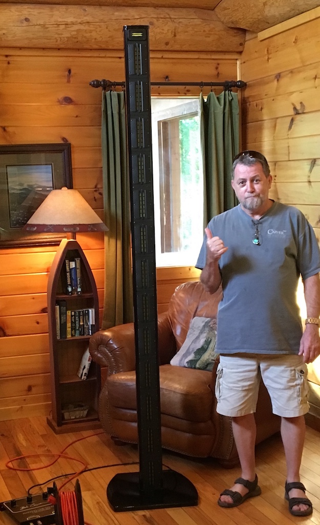
Did I mention amazing? See below. The Bobfather's new speaker is pretty amazing too. It's 88 inches tall with 13 forward firing ribbons and 22 side firing mid-woofers in each tower. The pair is bi-amped with a quad of Black Beauty tube amps and there's a Sunfire SubRosa sub woofer in the mix too. They will do 120 decibels without breaking a sweat and the sound is HUGE.
Tyu, you being an old Carver salesman will love this too:
Your last post, especially attachments 1 & 3 were eye openers for me. I have confidence now that my speaker is close to optimal as is. And as I recall, I got the tip from you to omit the R1 resistors and keep the 1Ohm on the primary.
I was groping around like a blind man in a brothel when I started the build but thanks to you and Golfnut, I have an amazing speaker!
Did I mention amazing? See below. The Bobfather's new speaker is pretty amazing too. It's 88 inches tall with 13 forward firing ribbons and 22 side firing mid-woofers in each tower. The pair is bi-amped with a quad of Black Beauty tube amps and there's a Sunfire SubRosa sub woofer in the mix too. They will do 120 decibels without breaking a sweat and the sound is HUGE.
Tyu, you being an old Carver salesman will love this too:
Yeah, “real” transformers can be challenging to design if needing to match an ideal model response. A major part of the challenge is that most parameters you change to improve leakage inductance tend to make winding capacitance worse…and vise versa.…especially attachments 1 & 3 were eye openers for me.

I think we can all agree on that.I have an amazing speaker!
Thanks for the pic! I have yet to hear his new line sources, but I did get to check out the SubRosa at a show. I was pretty impressed with the anti-shake, or Stillbass™ technology. Basically, uses a base shaker driven with appropriate magnitude and phase to cancel the vibration imparted to the enclosure by the high mass woofers.The Bobfather's new speaker is pretty amazing too. It's 88 inches tall with 13 forward firing ribbons and 22 side firing mid-woofers in each tower. The pair is bi-amped with a quad of Black Beauty tube amps and there's a Sunfire SubRosa sub woofer in the mix too. They will do 120 decibels without breaking a sweat and the sound is HUGE.
where I can download esl_seg_ui?
I'm not sure this is the file you're referring to but it's the one I used to design my segmented speakers:
https://www.diyaudio.com/forums/pla...periences-esl-directivity-10.html#post5441902
esl_seg_ui is not a single standalone executable file.where I can download esl_seg_ui?
It is a MATLAB utility that you need to download a set of folders and files for it to work.
The files can be downloaded from the attachments in Post #39 of this thread.
Step by step instructions for downloading, unzipping, and running the utility can be found in Post #79.
@Bolserst,
Sorry, for stealing this topic, but I'm trying to send you a PM with some questions, however it appears your mailbox is full? Do you perhaps happen to have a different means of contacting you? I have some magnetostat related questions pertaining to calculating net panel sensitivity based on magnet strength etc. I'd appreciate discussing the specifics with you if at all possible.
Sorry, for stealing this topic, but I'm trying to send you a PM with some questions, however it appears your mailbox is full? Do you perhaps happen to have a different means of contacting you? I have some magnetostat related questions pertaining to calculating net panel sensitivity based on magnet strength etc. I'd appreciate discussing the specifics with you if at all possible.
- Status
- This old topic is closed. If you want to reopen this topic, contact a moderator using the "Report Post" button.
- Home
- Loudspeakers
- Planars & Exotics
- Segmented Wire Stator ESL simulator (esl_seg_ui)