Hi everybody
I will try to make a mini planars for computer use.
the idea is to make a prototype for evaluation, an then a workable pair.
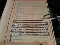
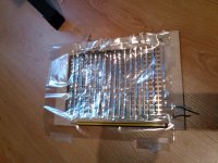
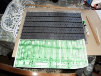
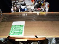
For now I have the frame and the foil, the magnets will arrive within a week.
however there are some problems to be solved, the first one is the low resistance of the foil; the first measure is 0,6 Ohms, bad thing.
The posible solutions are using a foil of 0,3 mm wide instead the actual 0,5 mm. this probably rise the impedance to 1 Ohm.
Another solution is doubling the length by replicating the pattern on the other side of the membrane, i.e. making a doble layer membrane, with a expected total resistance of 2 Ohms. This will be fine for the amplifier, with the addition of a series resistance of say 2 Ohms.
the active surface of the membrane is 10x18 Cm
What do you think?
Any help is welcome
Pedro
I will try to make a mini planars for computer use.
the idea is to make a prototype for evaluation, an then a workable pair.
For now I have the frame and the foil, the magnets will arrive within a week.
however there are some problems to be solved, the first one is the low resistance of the foil; the first measure is 0,6 Ohms, bad thing.
The posible solutions are using a foil of 0,3 mm wide instead the actual 0,5 mm. this probably rise the impedance to 1 Ohm.
Another solution is doubling the length by replicating the pattern on the other side of the membrane, i.e. making a doble layer membrane, with a expected total resistance of 2 Ohms. This will be fine for the amplifier, with the addition of a series resistance of say 2 Ohms.
the active surface of the membrane is 10x18 Cm
What do you think?
Any help is welcome
Pedro
Attachments
Hi HenryHi everybody
I will try to make a mini planars for computer use.
the idea is to make a prototype for evaluation, an then a workable pair.
For now I have the frame and the foil, the magnets will arrive within a week.
however there are some problems to be solved, the first one is the low resistance of the foil; the first measure is 0,6 Ohms, bad thing.
The posible solutions are using a foil of 0,3 mm wide instead the actual 0,5 mm. this probably rise the impedance to 1 Ohm.
Another solution is doubling the length by replicating the pattern on the other side of the membrane, i.e. making a doble layer membrane, with a expected total resistance of 2 Ohms. This will be fine for the amplifier, with the addition of a series resistance of say 2 Ohms.
the active surface of the membrane is 10x18 Cm
What do you think?
Any help is welcome
Pedro
I'm not thinking on a push pull arrangement, but on puting aluminium foil on both sides of the membrane.
Does anybody have tried this?
And about the resistor... Which value?
An 3 Ohm resistor will eat almost all the voltage, I suposse...
Hi Oshifis
Where can I find a matching trafo?
You can use an impedance matching transformer.
BTW I have seen a planar PC loudspeaker, same size as a normal PC speaker (except it is flat).
Where can I find a matching trafo?
I would use the epsilon layout which increases the length of the foil it also increases the sensitivity significantly. I wouldn't do a push pull design, I have tried several but there is no significant increase in sensitivity compared to the epsilon layout!!
The epsilon layout seems very interesting.
The magnets are too slim, thought, so lets see
Thanks for the help
Hi Henry
I'm not thinking on a push pull arrangement, but on puting aluminium foil on both sides of the membrane.
Does anybody have tried this?
And about the resistor... Which value?
An 3 Ohm resistor will eat almost all the voltage, I suposse...
I wouldn't put foil on both sides of the membrane, this will double the weight and make it less sensitive! The resistor depends on the resistance of the foil and whether you want a 4 ohm,8 ohm or 16 ohm to go with your amplifier. The resistor hardly has a effect on the sensitivity.
The epsilon layout seems very interesting.
The magnets are too slim, thought, so lets see
Thanks for the help
The epsilon layout is the best I speak from experience as I have been building planars for over 20 years.The magnets can be the size you require you lay out the foil to fit the magnet sizes.
using this layout you won't get much sound.THE EPSILON LAYOUT IS A MUST.Hi everybody
I will try to make a mini planars for computer use.
the idea is to make a prototype for evaluation, an then a workable pair.
For now I have the frame and the foil, the magnets will arrive within a week.
however there are some problems to be solved, the first one is the low resistance of the foil; the first measure is 0,6 Ohms, bad thing.
The posible solutions are using a foil of 0,3 mm wide instead the actual 0,5 mm. this probably rise the impedance to 1 Ohm.
Another solution is doubling the length by replicating the pattern on the other side of the membrane, i.e. making a doble layer membrane, with a expected total resistance of 2 Ohms. This will be fine for the amplifier, with the addition of a series resistance of say 2 Ohms.
the active surface of the membrane is 10x18 Cm
What do you think?
Any help is welcome
Pedro
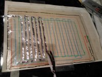
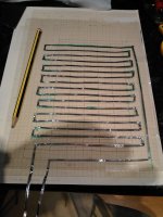
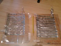
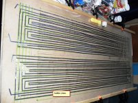
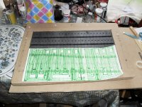
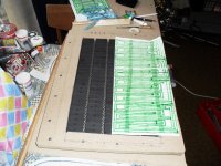
New membrane
Reducing the width of the aluminium strip from 5 mm to 3 mm has rised the resistance to 1.2 Ohm
Doubling the pattern on the other side of the membrane will put the resistance on 2.5 Ohm with a minimal amount of weight.
Maybe with a resistance of 2 Ohms in series this will make interesting sounds without burning any amp...
I will try to post some pics later
the pics
Reducing the width of the aluminium strip from 5 mm to 3 mm has rised the resistance to 1.2 Ohm
Doubling the pattern on the other side of the membrane will put the resistance on 2.5 Ohm with a minimal amount of weight.
Maybe with a resistance of 2 Ohms in series this will make interesting sounds without burning any amp...
I will try to post some pics later
Attachments
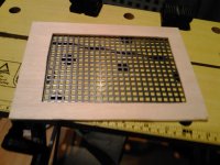
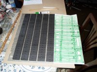
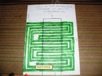
The epsilon affair
I've made some calculations and the Epsilon layout is possible with the magnets availables.
also, the resistance is expected to be in the 2 Ohms region, so a doble layer will put it in a tolerable region for the amplifiers.
I expect the magnets to arrive monday or tuesday.
by that time I will try to make an epsilon membrane.
Thanks for the advise
using this layout you won't get much sound.THE EPSILON LAYOUT IS A MUST.
I've made some calculations and the Epsilon layout is possible with the magnets availables.
also, the resistance is expected to be in the 2 Ohms region, so a doble layer will put it in a tolerable region for the amplifiers.
I expect the magnets to arrive monday or tuesday.
by that time I will try to make an epsilon membrane.
Thanks for the advise
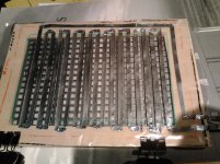
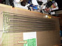
I did build a A4 sized planar but it wasn't very sensitive. Then I decided to try the epsilon layout, and rebuild some of my normal designs, best thing I ever did! I did build one double layout with gaps between magnets. A 4'x 2' size using 50 x 25 x 10 ferrites. Gluing the ferrites was a bind when I moved it 25 of them came undone, not worth the effort and would be nigh impossible using neos. So I built a 60 x 40 cm one using ferrites with no gaps and it was as loud as the big one with gaps!! Then I decided to use some 50 x 12.7 x 6 mm neos which I had used for another design which wasn't very successful.I have finished the pair and they are about 5db louder than my other designs.It weighs 16lbs and is 60 x 40 cms. I will build the other one to my 4' x 2' using ferrites with the epsilon layout. You get better bass with the bigger one. The impedance of the big one is 9.6 ohms and the 60 x 40 cm one is 6.3 ohms. Use a decorating roller to run over your tape, it flattens all the bubbles etc.
Take your pick these are all based on the epsilon layout.Some have been changed to go with different magnet layouts and different sizes.All the best.
Attachments
My Apogee's use them same Voice Coil pattern.
Just to set the record straight.
And I thought the main Idea on the Epsilon panels was that a Rubber surround is used to support the diagphram rather than mounting it directly to the frame,
http://www.diyaudio.com/forums/planars-exotics/200038-analysis-epsilon.html#post2775951
Keep up the great work guys !!
jer
Last edited:
I've never seen an Apogee up close to work out layout, the point of the epsilon layout was increased sensitivity by using all the magnet area. Not just the rubber surround. The big increase in sensitivity has nothing to do with the rubber surround.I suppose I could call it the epsilon apogee layout.My Apogee's use them same Voice Coil pattern.
Just to set the record straight.
And I thought the main Idea on the Epsilon panels was that a Rubber surround is used to support the diagphram rather than mounting it directly to the frame,
http://www.diyaudio.com/forums/planars-exotics/200038-analysis-epsilon.html#post2775951
Keep up the great work guys !!
jer
Here are some closeup pictures of the Apogees and it is a little hard to tell as the end of the loops are hidden by the frame,
http://www.diyaudio.com/forums/planars-exotics/196631-apogee-speakers-construction.html#post2711316
But, you are on the right track and the more loops that you can get in there the more efficiency you will get.
The thing that the Apogees suffer from ( besides from not using NEO's) is that there is only one loop per row of Magnets.
jer
- Status
- This old topic is closed. If you want to reopen this topic, contact a moderator using the "Report Post" button.
- Home
- Loudspeakers
- Planars & Exotics
- Mini planar magnetic using neos