Where is the other terminal of the bias supply connected to?
Were it should be ...it a bias... it stans on it own....who that would like to get the best sound thay could ...would wont to put one side of a bias tranfourmer AC winding that in the Acoustats would be 750v AC....Now if the earth is there with all it noise... it would on paper be 0...not what i call hi end sound but will work....let the bias be on it own.... sounds best
I understand you prefer to not connect the earth ground from the mains power to the bias supply.
That was not my question.
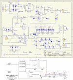
The bias supply still needs to be connected somehow to the stators, or the diaphragm won't charge up since it is in reality one plate of a capacitor with the stators being the other plate. I was wondering if ML retained the bias supply connection to the center tap, or moved it to the front stator along with the audio input ground reference. After rummaging around on the ML forum for a while I found the attached diagrams where you can see that the bias supply ground is connected to the front stator thru connector BB4 rather than the center-tap.
Since curved ESLs always have an issue with the diaphragm collapsing toward the rear stator, I wonder if having the front stator directly connected to the bias supply ground(with the rear stator connected to ground through the transformer secondary) encourages the diaphragm to pull toward the front stator rather than the rear stator when the bias supply is energized. This would be advantageous for curved ESL, but not flat ESLs. Hmmmm....intersting.
.
.
.
Attachments
So you say...
The bias supply still needs to be connected somehow to the stators, or the diaphragm won't charge up since it is in reality one plate of a capacitor with the stators being the other plat
This is Not true!.....I have 6pr of ESL here now...it works great...get that Diff.AC noise out...For better sound.
So you say
Since curved ESLs always have an issue with the diaphragm collapsing toward the rear stator, I wonder if having the front stator directly connected to the bias supply ground(with the rear stator connected to ground through the transformer secondary) encourages the diaphragm to pull toward the front stator rather than the rear stator when the bias supply is energized. This would be advantageous for curved ESL,
I dont buy this......but you can.....On paper mybe...Acoustats only has flat panels...SE setup works great...An sounds better than ever...
I have been living with this for a long time.....An just wont to share with other....i gess this is new for you....you need a pr of ESL so you can gives this a try?...An not just talk.
But your the same guy who think you can hang a 50cent doid brdg on the outputs of my $5k amp... An you say YOU cant hear it....it a limiter...the word means......to limit...I dont wont a ESL i have too....look to me like you are hellbent on being right...All i wont is to get the best sound i can...
I have posted these pic right here be for....but in the bottem pic... there is no centap...an were the neg coming from the amp an gose to the board is the only neg. going to the tranfourmer an panel.....look if you dont have to add AC noise in the bias why would you???
thanks
Hello Tyu,
Um...there must be something lost in translation here...
I wasn't disagreeing with your posts about ML moving the ground reference from the center tap to the front stator.
I was only trying to determine how they connected the bias supply since I could not figure it out from your comments or diagrahm in post#19
There is no right or wrong here. ML did what they did.
I've been listening to, building, and repairing ESLs for almost 20 years now and I find there are always new things to learn.
My apologies to the OP for the topic detour.
Sheldon-
Years ago, I visited the Gibson guitar factory. They have a saw that cuts the kerfs for the frets in the fingerboard in one pass. A lot of very thin blades were spaced on a single arbor at appropriate spacings.
I can cut dados up to about 1" wide with my old table saw. A number of blades spaced correctly could do 8 or so slots in a pass. They do make very thin blades for plywood and plastics- just need to find 'em. Makita makes them, but the arbor hole is small. When I find the blades, I'll let everyone know.
Is your Incra fence aftermarket?
Jay
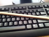
The TIG wire is 1/16" in 3 foot lengths I have a welding shop nearby that I would by it the pound and they would let me bring back the really bad ones and rejects and swap them out.
I tested them by rolling on a flat surface.
Then to assemble them I would lay out a layer of them in and offset the length of every other one and solder on the end support rods.
Then I got smart and made a comb tool with 8" tines to do the spacing as I soldered on the support rods.
They are spaced the same diameter as the TIG material 1/16".
Building a jig can be very easy with enough room as I did this on the top my desk.
The hardest part was getting enough heat to do the job as I did burn up one Radio Shack solder gun.
With a jig it would be possible to use something with more heat such as a propane torch with a large soldering tip.
I had thought about coming up with some sort of contact welding technique If decide to do more.
I have made 6 so far and I only need 2 more for some 6 foot panels.
I am going to polish them and give them a new coat of copper plating and paint them with clear acrylic,
Gold would look awesome as well!!
My plans have slightly changed and I am thinking about keeping these at 3 feet and try segmentation on these as the mod will be just a cut to the supporting bars.
Or do a two way panel using the 2 spare stators cut into smaller sections for the tweeter section.
I will then pair each panel three of the 8" subs that I have left as there are 6 left.
I project an 118db for a pair of speakers and flat from 25hz on up.
This will be my first standalone system.
Here is the link to my proposed sub system,
http://www.diyaudio.com/forums/plan...uch-thing-dipol-kick-chest-2.html#post2616546
It is the purple line in the charts.
Cheers!
jer")
I tested them by rolling on a flat surface.
Then to assemble them I would lay out a layer of them in and offset the length of every other one and solder on the end support rods.
Then I got smart and made a comb tool with 8" tines to do the spacing as I soldered on the support rods.
They are spaced the same diameter as the TIG material 1/16".
Building a jig can be very easy with enough room as I did this on the top my desk.
The hardest part was getting enough heat to do the job as I did burn up one Radio Shack solder gun.
With a jig it would be possible to use something with more heat such as a propane torch with a large soldering tip.
I had thought about coming up with some sort of contact welding technique If decide to do more.
I have made 6 so far and I only need 2 more for some 6 foot panels.
I am going to polish them and give them a new coat of copper plating and paint them with clear acrylic,
Gold would look awesome as well!!
My plans have slightly changed and I am thinking about keeping these at 3 feet and try segmentation on these as the mod will be just a cut to the supporting bars.
Or do a two way panel using the 2 spare stators cut into smaller sections for the tweeter section.
I will then pair each panel three of the 8" subs that I have left as there are 6 left.
I project an 118db for a pair of speakers and flat from 25hz on up.
This will be my first standalone system.
Here is the link to my proposed sub system,
http://www.diyaudio.com/forums/plan...uch-thing-dipol-kick-chest-2.html#post2616546
It is the purple line in the charts.
Cheers!
jer
Last edited:
Jer-
I know this is late in the game for your project, but your local welding shop may have or know of someone who has a spot welder. If you can make your alignment fixture stable and portable, the grids can be heat (spot) welded quickly and easily.
It takes only a second or two per weld, so even if you're being charged by the hour, the cost won't be much-
Great work so far, and good luck completing your project.
Jay
Well it has been 6 years since a had made those and they are still sitting around here.
So ,that might give you an idea of how far behind I am, he,he,he.
I have thought of building my own spot welder to do the job as well and I did a lot of research on the subject and will be some that I can do quite easily.
I did pick up a cheap TIG welder and this might work well as a power supply and all I have to do is come up with the contact apparatus .
I am thinking about building one the same size as my little panels to see if it would have the same efficiency as per size.
This would be a much easier construction method than the wire mesh method that I have been doing.
The sharp edges of wire prove to be difficult to seal at times as well as getting a consistent coating thickness across all of the wires.
Most all of my samples came out with a thicker coating on X wires than the Y wires and spraying them with paint always risks the closing of some of the holes.
Not to mention air borne debris, and, The time it takes to try and correct these issue's after they occur.
Very labor intensive ,But minimal costs with great results.
I keep all of these factors in mind should I do decide to build a few very large panels strictly for bass use.
It has been a very tedious process but I finally got my little panels to withhold a bias of 10Kv without arcing at a .072" D/S spacing.
So we will see shortly as to how well they will perform.
10kv easily jumps a .5" to .75" gap and packs quite a wallup when it does leaving 1/8" or bigger hole in the mylar along the way.
These are the types of voltages that you are looking at if you plan on doing a bass panel with a large D/S spacing.
It would be insane and a waste expensive wide diagphram material to try to attempt with out first addressing these issue's.
Both diaghrams now have holes in them and need to be replaced now and the one had survived 7 years with few damages and the one survived the last catastrophic failure without any at all.
But that is the cost of raising the voltages,Luckily they are just small panels.
jer
Jer-
If you have a small TIG welder, you're on the right path. TIG welding is very much like brazing, except you are using an arc for heat instead of a gas torch. TIG requires you have a shield gas to prevent the weld from being contaminated by atmospheric O2.
With steel, you do not need an exotic gas- CO2 will work nicely.
It's going to take you some practice, but you should be able to master the technique. You should remove the copper from the material you are welding in advance. You can plate it back on later.
I'm wondering why you are shooting for such high bias voltages. The panels I have are happy in the 1,5-2 KV range, and my step-up ratio is 50:1. The spacing between the stators and diaphram is roughly .1"- double sided foam tape.
I get more volume than I can stand when I play them, and I haven't yet had an arc-over in either dusty desert or sopping southern humidity conditions.
Hmmmm.....CO2, Interesting,thanks for the tip!!!
Sadly I don't have a gas system yet, But it will weld with some 1/16" rod so I know there is enough power from the unit.
Right now I am working with rather small panels and the higher I raise the bias voltage the louder and more efficient they get.
Where the limit is I am not sure some say that it is the breakdown of the air between the stators and I have approached this before at 5kv and at 7.5Kv they got even louder even though they were starting to breakdown and arc at this point.
A higher voltage would (if it works as I plan) will allow me to use more turns on my primary winding thus allowing the transformer a lower frequency before the onset of core saturation.
With A larger panel you have the advantage of surface area making up the difference. But using a wider panel panel you increase the beaming qualities at the highest frequency's.
In order to make up the low frequency defficiency with a narrow panel you must increase its excursion capabilities.
I have already reach this point with at around 200hz with my D/S of .072 and 5kv of bias.
My next frames will be about .043 thicker a little more than a 50% increase of D/S and warrants the increase of bias voltage to maintain the same efficiency or close to it.
Taking all of these things in perspective and applying them to a larger panel system could yield some panels of incredible SPl capabilities.
Without the need of a 1000 watt amplifier to drive them properly.
In the very first ESL articles from Roger sanders and David P. Hermeyer they were struggling to get to 110db.
But of course we have surpassed that now so the next step is the 120 to 130db range.
That may seem like an outrages figure but not when you are in a very large room as even an 18 foot distance from the loudspeaker is about a 10db drop in the sound level.
This may be over kill for your average home use but I am think beyond the box.
Also many may not have the room for such a large panel system.
The biggest complaint that I have read about smaller ones that have been built is that they didn't go loud enough.
I have pushed this little panel so hard that it scares you out of the room and I can hear it perfectly when I go to the downstairs of my house as well.
That is pretty darn loud and unfortunately I didn't have a working SPL meter then, But I do now !
About the level of the bias voltage,
As I was testing my stators for leakage I noticed that the wire feeding the panel would suck down to my desk where the wire was arched and when the voltage was reduced to 0v the wire would of course snap back to its original form.
This was at a mid setting of 6.8kv.
And as I increased the voltage to a full 13.8kv the wire became flatter and then popped back up to a normal position at 0V again.
I did this repeatedly at different voltage settings.
Okay now, May I remind you that every thing was sitting on a glass plate and there was not any corona discharge coming off the Clip lead wire insulation feeding the stator from the power supply.
This was due to pure electrostatic force and no current was involved.
If there was any current drawn I would have detected it by the sound of the fan of the power supply as it ramps up to compensate for the voltage drop when current get drawn from it.
Interesting?
This is why I am sceptical about what the actual limits are.
Just a few thoughts and things that I have observed.
jer
Sheldon-
Years ago, I visited the Gibson guitar factory. They have a saw that cuts the kerfs for the frets in the fingerboard in one pass. A lot of very thin blades were spaced on a single arbor at appropriate spacings.
I can cut dados up to about 1" wide with my old table saw. A number of blades spaced correctly could do 8 or so slots in a pass. They do make very thin blades for plywood and plastics- just need to find 'em. Makita makes them, but the arbor hole is small. When I find the blades, I'll let everyone know.
Is your Incra fence aftermarket?
Jay
Yes, my incra fence is an add-on to my table saw.
The ticket here is to make an arbor that holds one or more slitting saws. I'd consider an arbor of a couple inches long that holds a few blades with spacers between. It's really a trade-off on number of cuts vs. how many blades you are willing to buy. They aren't painfully expensive, but say 50 of them is starting to be.
Enco - Guaranteed Lowest Prices on Machinery, Measuring Tools, Cutting Tools and Shop Supplies
Since I've got a CNC mill, I can do the slots one at a time, and let the computer do the heavy lifting while I sit back with a tea and watch.
Sheldon,
Thanks for the link. Since you have the tool, use it. I'm going to look into the blades.
Your idea using resistors to EQ the panel is very interesting, indeed. I think I see what you have in mind, or at least I think I understand how it would work. I'm not too mathematical.
Your thoughts and progress would make a great topic for all of us should you decide to share---
Jay
Is that 3db down at 35 hz ..?
My Acoustat 2+2's played flat to 30 Hz in my 25 X 15 X 8 room. However this was with an entire upper bass that was +6 to 10dB. I could play music with peaks of 103 dB before my amp (Moscode 600) shut down.
So I should think that a bass panel necessary to equal the 2+2's should be their size. Unless smaller but with wings.
Now I use the Moscode for H frame 15" woofer (open baffle) with Full Range on top.
Now, with bass peaks hitting 110 dB I can't see the woofers moving (must be far less than a millimeter) and because its open baffle (H frame) I get a little confused on the size necessary for bass panel / d/s spacing necessary for bass on said panels.
I did take the socks off my 2+2's for a while. Couldn't see them move on bass peaks either, but did see reflected light on them "shimmer".
Paul
Sheldon-
How are you planning on cutting the guide channels for the stator wires on your spacers? I have an idea forming, but I need to try it in the shop.
My very first wire ESL project involved 8" wide panels built with 14 gauge wire. I figured slotted crossbars would be the way to go. So, having access to a table saw I went looking for a blade of proper thickness. I finally found one...cut slots just a hair over 1/16" wide.
Rather than cutting slots in already dimensioned crossbars, I cut slots down the length of the crossbar material. Then when all the slots had been made, I could cut the cross bars to width. I chose to use 50% open area to make incrementing the rip fence easier. Also, I cut an even number of slots(62) working from the middle out in a symmetric fashion so I could cut two slots for each setting of the rip fence by flipping the board around 180 degrees.
Attached is a pic of one of the leftovers I kept as a souvenir.
Attachments
Now, on to my project. I have decided to go with perforated plastic stators. This solves two problems- it insulates, and I can work it in my own humble shop.
Metal stators are hard to cut to size if you don't have a shear, and insulating them can get expensive, especially if you powder coat them.
I feel it is much easier to apply a coating (Aqua Dag) that will spread a charge on an insulator than trying to insulate a solid metal panel, especially at very high potentials.
I am going to use the double-sided tape method of contruction, but since I want to have a bit more spacing, I'm going to lay down a layer of UHMW tape on the stators. I'll have to play with this to determine the "correct" thickness. Fortunately, acetone will loosen the tape adhesive for easy rebuilds.
Transformers- I currently have a pair of 90:1 trafos that worked well at 2 KV. I want to up the "bias" voltage considerably, so 'llI have to hipot them to see where they will break down. I may end up winding my own- 40 Lbs? So many mysteries---
- Status
- This old topic is closed. If you want to reopen this topic, contact a moderator using the "Report Post" button.
- Home
- Loudspeakers
- Planars & Exotics
- ESL woofer- anybody game?