I haven't seen any tall and narrow commercial planar magnetic systems that use a central tweeter section flanked by midrange sections, all sharing a common diaphragm. I'm envisioning something analogous to ESL systems that use resistors to progressively limit the bandwidth of the signal sent to sections of the diaphragm as the distance from the tweeter increases (except using capacitors instead of resistors). My aim is directivity that doesn't vary strongly with frequency. Have I missed the examples where this has been done or is there a reason it's a bad idea? I'm considering a one-sided (non-push-pull) design mimicking the quasi-ribbon midranges in Magneplanar speakers, but using NdFeB magnets.
Few
Few
Hello Few,
The only example I can recall of a quasi-ribbon using a concept like you describe is the Neo8 PDR.
"...the patent pending PDR(progressive drive and radiation) technology allowing for a significantly wider horizontal dispersion above 8 kHz. The PDR technology provides progressively increasing excitation force from the periphery to the center portion of the diaphragm, while creating frequency dependent acoustic dampening and absorption across the diaphragm...."
It is interesting that the idea has not been used on a larger scale transducer similar to ESLs. Perhaps the problem is that the thin/light aluminum conductors required for mid-tweeters to be able to reproduce 20Khz, are not be able to handle the current and resulting heat needed for low frequency reproduction. So, you wouldn't be able to segment a quasi-ribbon the way you can an ESL.
BTW, I think your ladder network would need to be made from inductors, not capacitors as you mentioned.
Temperature might be a concern but it'll probably be trickier just to get everything else to work out.
There are several considerations for choosing the foil thickness, width, length, and resistance. I re-derived the equations relating all of those, and did a bunch of planar driver layout-type sample calculations, which are posted in the Planar Speaker Asylum thread at the following URL:
RE: "If we replaced the wire with foil that had 1/4th the mass and 4X the resistance per inch" ... - tom_gootee - Planar Speaker Asylum
Selecting "all" at the top should also show the other posts in that thread, where I did significant related calculations.
As far as the heating effects are concerned, it should be simple to calculate. The total power dissipated would just be i²R for the resistance of the whole conductor. So the power dissipated per inch should just be i²R/Length in inches. I can't remember offhand how to calculate the constant factor to get temperature rise, from that. But it is on line, for things like copper PCB traces. You'll probably have to convert any equations you can easily find from copper to aluminum, or ask in one of the physics forums.
Thanks for the responses.
It sounds like the PDR approach has some aspects in common with what I described but also some differences. The idea is to drive the center of the membrane harder than the edges and use acoustic absorption (foam or felt) to reduce the high frequency radiation from the edges. Do I have that right? If so, late night thinking (always dangerous) suggests the high frequency absorption would have the same effect as the inductor ladder (thanks for catching my capacitor mistake) approach I described. It would just limit the bandwidth acoustically instead of electrically. I recently saw another company doing the same thing. I'll have to figure out who that was.
The part about driving the center of the diaphragm harder than the edges at first had me thinking the diaphragm would act as if it were curved (like a Martin-Logan ESL) but that can't be right. The diaphragm might approximate a section of a cylinder when driven, but the concavity of the cylinder would switch as the diaphragm vibrated. It wouldn't have the fixed concavity of a truly curved diaphragm. I guess I'm not really sure what's achieved by the "progressively increasing excitation force."
Thanks also for the comments on conductor mass and current capacity. Since I'd be building from scratch the strength of the magnetic field is not a fixed quantity. I believe Magneplanar does not use NdFeB magnets, although I'd be happy to be corrected on that if I'm wrong. If I'm right about that then I'd be interested in figuring out whether increasing the magnetic field provides a useful amount of wiggle room on the mass or current capacity fronts. Thanks for the link that supplies many of the pertinent equations.
I would think that going to neo magnets, which Magnepan does not use, would give a huge increase in wiggle room(s)!
Thinking (late-nightedly) about membrane convexity or concavity, I guess that theoretically you could use superimposed DC voltages to push or pull the conductors (and thus the membrane) into other-than-flat shapes. And, for example, it seems like you could curve the magnet array and then force the membrane to conform, with proper clearances, only when the superimposed DC voltages were present.
Thinking (late-nightedly) about membrane convexity or concavity, I guess that theoretically you could use superimposed DC voltages to push or pull the conductors (and thus the membrane) into other-than-flat shapes. And, for example, it seems like you could curve the magnet array and then force the membrane to conform, with proper clearances, only when the superimposed DC voltages were present.
Few: have you had a look at the Sumo Aria? This was designed and manufactured by Highwood Audio in Calgary Alberta Canada in the late 80's early 90's. Superb dispersion, we measured 10 KHz at rt angle to the diaphragm edge we used a 1.25 inch voice coil to drive a large Mylar diaphragm. Think of it as a tweeter with the worlds largest suspension. IMO they did a much better job compared to a Quad ESL63 with about the same radiating area. Very simple and easy load. Zero components in the signal path. Best regards Moray James.
Clever trickHint: Using DC can also be advantageous when you are positioning the conductors and for holding them in place while the adhesive cures.

@Few
I had a thought while driving home last night of an acoustic reason why segmented quasi-ribbons may not work like segmented ESLs. It concerns % open area and the resulting response of each of the ribbon segments. Before I bother going any further, can you confirm what typical open area is for the back plate of the single ended quasi ribbon? I remember examining an MMG some years ago and was surprised to find only rows of very small holes between the magnets. Estimated open area for the MMG backplate would be <10%. Is this typical?
Yes I am familiar with the Sumo Aria, but of course not as familiar as you are. Once I'm done not building my planar magnetic speakers and have finished not finishing my wire-stator ESLs, maybe I'll start (but not finish) a project to duplicate the Aria. Sounds like fun! The Aria seems like an elegant idea for sure. How was the impulse response?
Bolserst: I wouldn't have said that 10% open area is typical based on photos I've seen of planar magnetic systems but I haven't done a careful study. I'm surprised to hear that's what you saw, in fact. I was planning on much more open area (50% or a bit more) and then trying some felt or wool or one of the other usual suspects to absorb some of the high frequencies in the back wave and damp some of the cavity resonances. The openings in Bohlender-Graebener drivers look larger than the ones you've described
and pictures I've seen of the old Apogee woofer sections showed more open area, if I remember correctly (I can't seem to find the pictures even though they were posted here on diyAudio). In any case, I realize you're talking about high frequency drivers.
My goal in the present project is not to try to curve the membrane. I want to use driver width to control directivity on this one. Nonetheless, interesting ideas are always...interesting, and of course, appreciated.
Few
The Aria seems like an elegant idea for sure. How was the impulse response? Bolserst: I wouldn't have said that 10% open area is typical based on photos I've seen of planar magnetic systems but I haven't done a careful study. I'm surprised to hear that's what you saw, in fact. I was planning on much more open area (50% or a bit more) and then trying some felt or wool or one of the other usual suspects to absorb some of the high frequencies in the back wave and damp some of the cavity resonances. The openings in Bohlender-Graebener drivers look larger than the ones you've described
An externally hosted image should be here but it was not working when we last tested it.
and pictures I've seen of the old Apogee woofer sections showed more open area, if I remember correctly (I can't seem to find the pictures even though they were posted here on diyAudio). In any case, I realize you're talking about high frequency drivers.
My goal in the present project is not to try to curve the membrane. I want to use driver width to control directivity on this one. Nonetheless, interesting ideas are always...interesting, and of course, appreciated.
Few
Last edited:
Hello Few,I wouldn't have said that 10% open area is typical based on photos I've seen of planar magnetic systems but I haven't done a careful study. I'm surprised to hear that's what you saw, in fact. I was planning on much more open area (50% or a bit more) and then trying some felt or wool or one of the other usual suspects to absorb some of the high frequencies in the back wave and damp some of the cavity resonances. The openings in Bohlender-Graebener drivers look larger than the ones you've described
In any case, I realize you're talking about high frequency drivers.
I'm not talking about HF drivers, but single ended LF Magnepan drivers like what you want to use.
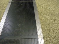
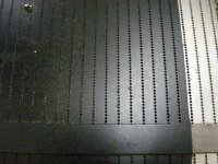
I did find my pics and notes from the MMG I repaired.
Calculated open area was right at 10%.
See attached pics.
I also found a DIY post with a pic of a Magnepan Tympani bass panel.
Holding calipers to my screen and a little math gave open area of about 20%.
http://www.diyaudio.com/forums/plan...speaker-using-neo-magnets-15.html#post2720764
You are right, I think pretty much all the BG drivers have 40% - 50% open area. But, they are also all push-pull. Not sure if there is a correlation there, as far as what % open area is needed to get reasonable sensitivity for single ended vs push-pull ribbons. Perhaps gootee will be able to enlighten us on the subject.
Understood...just like ladder network driven symmetrically segmented ESLs.My goal in the present project is not to try to curve the membrane. I want to use driver width to control directivity on this one.
The thought I had concerning the % open area, is that with ESLs, each segment of the ESL measures like it is suspended by it's lonesome in space with nothing around it. Each segment measures with a nice +3dB/oct slope. This allows the use of simple EQ with ladder resistors adding in more and more area as you work down in frequency. Adding in area at the correct rate to counteract the sloping response of each individual segment.
Now, once % open area gets down in the 10% range, each segment would act more like it is on a baffle board whose width is the sum of all the segment widths. In this case, if you measured the center segment, rather than sloping down, response would be pretty much flat till dipole cancellation starts. You will even see a bump in the response just before cancellation starts and also a notch or dip at twice that frequency, just like you would expect from a HF driver in the center of a wide baffle.
So my thought was....if the center segment is going to measure pretty much flat all by itself all the way down to dipole cancellation territory, a tweeter/woofer combo really makes more sense. And then, to avoid bump and dips in the tweeter response, better to move the tweeter off to one edge of the panel.
So, there you have it....random neural firings from texas...
Attachments
Last edited:
Hmmm, all very intriguing. Clearly I need to hit the reset button on my assumptions and make sure I'm not stuck in an "imagination" rut. I assumed you were referring to HF drivers when writing about the low open area panels. Bad assumption; thanks for the clarification. I think I also have a better sense of what your concerns were when you raised the issue of very small open area.
You raise (if I correctly understand what you intend to raise) an interesting point: There might be an important difference between the single-ended and push-pull situations. My gut inclination has been to use perforated steel with ~50% open area as a compromise between field strength and acoustic transparency. I'll be the first to admit that that staring point is completely pulled out of a place where the sun don't shine. I have no defensible reason for starting with 50% open area.
It seems reasonable to think that if the perforated steel plates act as acoustic resistors, then you'd want twice the open area in each panel if there were going to be two of them instead of one. Nonetheless, I wouldn't be shocked to find life ain't that simple.
I'm currently focusing on the mid and high frequencies because I'll be using a vertical array of six 8" woofers (open baffle) for the lower frequencies. I'm waiting to see how things look before deciding on a crossover frequency, but 500 Hz plus or minus an octave is where I was hoping to start.
Here are the starting points for my design:
1) NdFeB ("neodymium") magnets: 1" long by 0.25" x 0.25" cross-section, polarized across a 0.25" dimension.
2) Conductors cut out of foil that is 1.5" wide and 5.5 microns thick. I have a large roll of the stuff, and plan to use a rotary cutter and my mat cutter (for making mats for pictures) to cut uniform width strips. It seemed to work well on my first attempt.
3) Perforated steel backing to support the magnets and provide a bit of a pole piece.
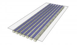
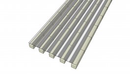
My calculations suggest that the foil will yield a resistance of 1 ohm if cut into strips 10 mm wide and 2 m long (10 ohms for 1 mm wide and 2 m long). The driver will likely be slightly less than 2 m tall (roughly 5') so I plan to use some combination of series and parallel connections to get the overall resistance to around 4 ohms. The physical arrangement I'm starting with is shown in the attached figure. It shows 0.25" wide foil strips glued to a mylar diaphragm, suspended above columns of magnets. I haven't shown the perforated steel support. The magnets will be arranged in the usual N-S-N-S- pattern going column-to-column.
I'd like to keep the magnet cost to the $300 territory for each driver, and the magnets are about $1 each. I'm still trying to decide how wide to make each driver (somewhere between 4 and 6 conductors wide) and of course have to decide how much height to give up to achieve the target width and stay within budget. I think I'll start with 0.25" wide conductors to match the 0.25" magnet widths. Some FEMM calculations showed that 0.25" spacing between columns of 0.25" wide magnets is a good starting point.
If I ignore any midrange/tweeter distinction for the moment and consider a widerange design, I could go for four foil conductors run in series, each 0.25" wide and 5' long, and reach the 4 ohm target. This would yield a radiating area that is a bit over 2" wide.
My gut says it would be nice to go for six such conductors instead of four but I'd either need to give up some driver height or start selling cookies to make the budget work. I haven't done any simulations to gain insights into what is gained or lost when giving up height for width, or vice versa. Advice would be welcome.
If I want to do the central tweeter thing I may need to use narrower conductors for that section so that I can reach a reasonable resistance with a smaller number of conductors (to achieve the narrow width necessary for a tweeter). Or, I could try to mimic Magneplanar's "true" ribbon tweeter. I think my foil is about twice as thick as what I'd want for that, though. I think they use about 2 micron thick foil, which would make sense if you want a practical resistance from a 2 m long ribbon of reasonable width.
1) NdFeB ("neodymium") magnets: 1" long by 0.25" x 0.25" cross-section, polarized across a 0.25" dimension.
2) Conductors cut out of foil that is 1.5" wide and 5.5 microns thick. I have a large roll of the stuff, and plan to use a rotary cutter and my mat cutter (for making mats for pictures) to cut uniform width strips. It seemed to work well on my first attempt.
3) Perforated steel backing to support the magnets and provide a bit of a pole piece.
My calculations suggest that the foil will yield a resistance of 1 ohm if cut into strips 10 mm wide and 2 m long (10 ohms for 1 mm wide and 2 m long). The driver will likely be slightly less than 2 m tall (roughly 5') so I plan to use some combination of series and parallel connections to get the overall resistance to around 4 ohms. The physical arrangement I'm starting with is shown in the attached figure. It shows 0.25" wide foil strips glued to a mylar diaphragm, suspended above columns of magnets. I haven't shown the perforated steel support. The magnets will be arranged in the usual N-S-N-S- pattern going column-to-column.
I'd like to keep the magnet cost to the $300 territory for each driver, and the magnets are about $1 each. I'm still trying to decide how wide to make each driver (somewhere between 4 and 6 conductors wide) and of course have to decide how much height to give up to achieve the target width and stay within budget. I think I'll start with 0.25" wide conductors to match the 0.25" magnet widths. Some FEMM calculations showed that 0.25" spacing between columns of 0.25" wide magnets is a good starting point.
If I ignore any midrange/tweeter distinction for the moment and consider a widerange design, I could go for four foil conductors run in series, each 0.25" wide and 5' long, and reach the 4 ohm target. This would yield a radiating area that is a bit over 2" wide.
My gut says it would be nice to go for six such conductors instead of four but I'd either need to give up some driver height or start selling cookies to make the budget work. I haven't done any simulations to gain insights into what is gained or lost when giving up height for width, or vice versa. Advice would be welcome.
If I want to do the central tweeter thing I may need to use narrower conductors for that section so that I can reach a reasonable resistance with a smaller number of conductors (to achieve the narrow width necessary for a tweeter). Or, I could try to mimic Magneplanar's "true" ribbon tweeter. I think my foil is about twice as thick as what I'd want for that, though. I think they use about 2 micron thick foil, which would make sense if you want a practical resistance from a 2 m long ribbon of reasonable width.
Attachments
I found the manufacturer I was searching for before: VMPS. They got an apparently hotly contested patent on an absorptive waveguide that improves directivity with minimal loss in broadband sensitivity (or so they claim).
VMPS patented CDWG | VMPS
This provides another way to achieve the frequency-independent directivity goal I'm after. I'm not sure it's the approach I want to adopt, but I thought I'd toss it into the mix.
Few
VMPS patented CDWG | VMPS
This provides another way to achieve the frequency-independent directivity goal I'm after. I'm not sure it's the approach I want to adopt, but I thought I'd toss it into the mix.
Few
I think that you might want to experiment with the spacing and foil width, by making a testbed with two short columns of magnets and one relatively short piece of foil, with no membrane. Then use a variable DC supply and a resistor in series to energize the foil. Check to see that you get only vertical forces on the foil, and for what different foil widths, distances from the magnets, and magnet spacings. If the magnetic field is not horizontal (i.e. parallel to the foil) everywhere your foil is, you might get some "sideways" force on the foil. You might need your foil to be narrower than 0.25 inch, for 0.25-inch magnet spacing.
I have read about an OEM version of the Bohlender-Graebener R75 which has a seperate etched narrow-trace serpentine tweeter in the center of the film, plus seperate etched wider-trace serpentine midranges on the right and left sides. This provides separate tweeter connections for amplifier drive as well as seperate midrange connections for amplifier drive. According to the document, this configuration allows tweeter compensation to generate 20Khz, plus improved high frequency dispersion from the narrower tweeter width. Delay could be added to the midrange traces to mimic a point souce, similar to the Quad 63 delay lines used to mimic a point souce.
Thanks Linesource, that's interesting. I haven't found anything about that on the web yet, but I'll keep poking around.
gootee: I have a 6"x10" piece of perforated steel for the purpose you described (1/16" thick with 0.25" dia holes in a staggered pattern and 0.31" center-to-center spacing). I also have 50 of the NdFeB magnets (1"x0.25"x0.25") to work with. My FEMM calculations suggested 1/4" spacing of 1/4" wide magnets would be a good starting point based on the straightness and uniformity of the field lines where the conductors would be but clearly some experimentation is in order. Because I'm using very thin mylar (3.6 micron from ER Audio) I also need to think about its behavior between the conductors. I don't think I want too much undriven diaphragm area.
I did a quick experiment with Scotch-weld 1357 neoprene adhesive last night. It seems to work well but it's a contact cement and requires coating both surfaces (Al and mylar) which is a little inconvenient. It's rated for high temperatures so I'm expecting to run into problems with the mylar getting distorted by hot conductors before losing the glue joint. It would be nice if neither one is an issue so I'll aim for high sensitivity without drawing too much current.
I have to figure out how to cut conductors out and glue them on to a stretched diaphragm while keeping everything nice and straight--preferably without putting glue anywhere except where there will be a conductor. I also need to figure out how to make electrical contacts to the very thin Al foil. Anybody know what the "pros" do in that regard?
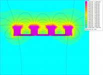
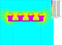
Following up on gootee's concern about the magnetic field lines, here's a FEMM simulation of 0.25" x 0.25" magnets on a steel plate, with a 0.375" gap between rows of magnets. If the conductors were placed about 1/8" above the upper plane of the magnets they would be in a region where there is significant curvature of the field lines, which implies the force wouldn't be in the desired direction.
On the other hand, those following the thread about the Analysis Epsilon repair will notice that the conductors in those speakers are not restricted to the region between magnets. The diaphragm seems nearly covered with conductors, most of which will sit directly above the magnets' faces, not over the gaps between the magnets.
Perhaps the fact that the diaphragm is clamped at the edges means you don't have to worry too much about forces parallel to the plane of the diaphragm because motion in that direction is constrained. Anybody happen to know how important it is to restrict the conductors to regions of space where the field lines run parallel to the diaphragm?
Attachments
Here's an attempt to find out if thin opposing magnets mounted above the primary magnets can help straighten the field lines without breaking the bank or obstructing the sound too much.
Left: 1/4" x 1/4" primary magnets and no opposing magnets.
Right: 1/4" x 1/16" magnets positioned 3/16" above the primary magnets.
The opposing magnets flatten the field lines. Does this matter and is it worth the extra cost and complexity? Several well regarded manufacturers use purely single-sided designs so that suggests things can be made to work well with a simpler system. The results with the opposing magnets look enticing, though.
Attachments
I'm doing a lot of replying to myself so I think I'll let this go after this post. I did want to point out before fading away that Baldin posted a new thread which answers some of the questions I raised here. Wisdom is using a central tweeter in a planar-magnetic system.
They also use two-conductor alternative to Magneplanar's single-conductor per magnet gap approach. The attached figure shows how I might modify the previously posted design to include a pair of conductors per gap.
Few
They also use two-conductor alternative to Magneplanar's single-conductor per magnet gap approach. The attached figure shows how I might modify the previously posted design to include a pair of conductors per gap.
Few
Attachments
Last edited:
- Status
- This old topic is closed. If you want to reopen this topic, contact a moderator using the "Report Post" button.
- Home
- Loudspeakers
- Planars & Exotics
- Planar magnetic with central tweeter?