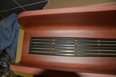
I didn't know this existed but I thought of a similar design myself in order to get more moving surface and a small width.
Like to hear from your experience.
Is there something done to prevent the membrane slapping onto the magnets?
Edmund
This i a clever design. But this statement from 6moons isn´t true
"By folding their midrange diaphragm faintly reminiscent of Heil"
The folds is exactly the same as the Oskar Heil idea. 1 fold will move like 10 folds. If it plays well, it dosn´t really matter. But the idea is Oskar Heils.
You actually loose sensativity with multi conductor runs. Yes its nessasary on the smaller drivers to get the ohms up to resionable level BUT for a given resistance it only goes down with more runs.
Hi lowmass, I am trying to understand the working of all of this.
Can you please elaborate what forces are at work here. WHY would the sensitivity become less with more conductor runs.
Lets suppose both the resistance and weight on the conductor will be the same. ( imagine a smaller or lighter conductor for the one with the more runs )
Edmund
Hi Edmond, I will give it a shot..
Basically if you keep the same foil thickness and you double the number of "runs" then you will increase the resistance of the ribbon by a factor of 4. So just to get the idea across lets say you start with a ribbon with a single run of foil and it has 1 ohm of resistance. ( in real world it would be much lower resistance but I choose this just to get point across). If you split that single run into 2 runs then each run is 1/2 width of original wich means the resistance of each run is 2 times greater than the wider original run. Now if you put those 2 runs in series you now have 4 times as much resistance as with one wide run.
Now lets say there is 10 volts peak in your signal to each of these ribbons. 1st one is one run and 1 ohm. So 10volts divided by 1 ohm eguills 10 amps through that single run ribbon.
Now take the 2 run version using same foil. Each run is 2 ohm ( 2 times the original wide run because its 1/2 as wide) and there is series so the total ohms = 4 ohms. So 10 volts divided by 4 ohms eguills 2.5 amps through that ribbon.
power is amps times volts so the single run ribbon is operating at 100 watts and the 2 run ribbon is operating at 25 watts. Thats a -6 db loss in sensitivity to double the runs!!
Remember this is "sensitivity" NOT efficiency.
You say "Lets suppose both the resistance and weight on the conductor will be the same. ( imagine a smaller or lighter conductor for the one with the more runs )"
The problem is if you use a lighter conductor the problem gets even worse. Not only will the resistance get even higher but with lighter ribbons the air mass starts to figure in more . Theres no free lunch here.
In the end you have to design by balancing all this stuff out to maximize sensitivity while not overloading the amp otherwise we would simply use a single run nearly short circuit ribbon on everything. AND it gets seriously trying as simply calculating these things all out does not result in great sound. There are many things that calcs and measurement eather cannot tell us OR we dont quite know how to interpret to a level where we can simply look at the data and know. Our God given tools can hear it but we dont nessasarily know what exactly is it in the design thats making it sound so good. Years and years of experaments tend to develop your ability in this area and you start refining mechanical properties to achieve desiered result. Sooo many times I have seen ribbon that measures great BUT sounds only good and others that measure good but have something special about their sound. That undefinable sumthin thing Ha..
Last edited:
@lowmass
Hallo lowmass,
Thank you very much for your detailed response, now I see why it is so very important to be as specific as possible.
I see what you mean but when I said : “Equal resistance and equal weight” I had something different in mind, I meant the resistance and weight of the entire conductor on the ribbon or planar, not the way you describe it.
OK I can understand what you are saying -so lets stick to that- except for two things.
1
The situation with 2 conductor runs has 2 times the L(ength) compared to the single run.
So there are 2 conductors of 2.5 Amps running through the magnetic field instead of one.
Wouldn't that make a difference, like more driving force etc?
2
My example with a “lighter” conductor. I mean just less weight and all other things the same.
Same resistance, same anything.
So there is no resistance going up and I don't know what you mean with lighter ribbons the air mass starts to figure in more.
As far as I know they all try to make a driver of zero weight, thinner and lighter, that gives more efficiency -sound pressure- and much easier high frequencies.
I don't mind learning something, so by all means correct me where I am wrong.
Ok well as for #1 - You caught me , I made a mistake. In my example the 2.5 amps should be times 2 because ther are 2 "runs". So its actually 50 watts not 25. So the sensitivity reduction is actually -3db not -6 db. Still its significant.
#2- Lighter weight does not always equate to higher sound pressure. There is always an optimum for a given size. If you take for example a small ribbon of say around 10 inches in length and about a half inch wide.The highest sensitivity will come from a ribbon of about 12 micron thickness. I know this from experience, not so much from calculation. Sure there may be some sonic benefits from going thinner BUT in any given size ther comes a point when you will start o loose sensitivity by going thinner.
With the lighter ribbons the mass of the diaphragm is so low that the weight of the air its moving is becoming a large percentage of the overall moving mass. Basically if you cut the mass in half you should gain about 6 db sensitivity BUT when the diaphragms mass is super low like a very thin ribbon or electrostat the air mass adds enough to swamp that effect out.
Also with ribbons you have that darn "slot" created by the magnets wich can add even more air load and lower sensativity again. Often this is somewhat overcome by the increase in magnet field strength of a deeper magnet slot but in the end you dont gain much in sensitivity.
I have built ribbons from tiny to huge and from 4 micron to 20 micron, in foil only cripped and "flat embossed " designs and plastic backed multi run designs in all thicknesses as well. I can tell you this. While ther are technical details that are fundamental to each such as the delicacy of the treeble that the 4 micron units will do, in the end each has strengths and weaknesses. The "ART" in all this is to get to know them all well and through much hard work learn to capitalize on each attribute to ultimately land a great design.
Sure a lot of the tecnical knowladge is needed BUT theres still no substitute for experience, judgment , and talent.
BTW my early reference was a pair of ribbon headphones I made. I simply unrolled a metalized film capacitor ad heat formed the film into a gorugated diaphragm about 1inch wide and 3 inches long, mounted these between some magnets on a small frame and then to a strap to hold the whole mess on my head. The diaphragms were 3 micron polyester film with a coating of aluminum so thin you could see through it and the resistance was about 5 ohms. You could connect them direct to the amp ! Basically you had a direct drive ultra low mass diaphragm. Blackest background ive ever heard.
Last edited:
Ok well as for #1 - You caught me , I made a mistake. In my example the 2.5 amps should be times 2 because ther are 2 "runs". So its actually 50 watts not 25. So the sensitivity reduction is actually -3db not -6 db. Still its significant.
#2- Lighter weight does not always equate to higher sound pressure. There is always an optimum for a given size. If you take for example a small ribbon of say around 10 inches in length and about a half inch wide.The highest sensitivity will come from a ribbon of about 12 micron thickness. I know this from experience, not so much from calculation. Sure there may be some sonic benefits from going thinner BUT in any given size ther comes a point when you will start o loose sensitivity by going thinner.
With the lighter ribbons the mass of the diaphragm is so low that the weight of the air its moving is becoming a large percentage of the overall moving mass. Basically if you cut the mass in half you should gain about 6 db sensitivity BUT when the diaphragms mass is super low like a very thin ribbon or electrostat the air mass adds enough to swamp that effect out.
Also with ribbons you have that darn "slot" created by the magnets wich can add even more air load and lower sensativity again. Often this is somewhat overcome by the increase in magnet field strength of a deeper magnet slot but in the end you dont gain much in sensitivity.
when going even lighter does increase the high end.
The performance of planar drivers can be predicted by theory to a surprising degree. Walker (of QUAD electrostat fame) pitched the remarkable extent to which theory could predict the performance of electrostatic speakers as one of their many virtues.
For more recent ribbon-related examples check out Bolserst's posts on this forum. For example, you might begin with post #202 in the "...reductio ad minimum" thread. He provides several other compelling examples in that thread so it's worth seeking them out.
Few
For more recent ribbon-related examples check out Bolserst's posts on this forum. For example, you might begin with post #202 in the "...reductio ad minimum" thread. He provides several other compelling examples in that thread so it's worth seeking them out.
Few
Yes its tru that the basic measured performance can be predicted quite accurate. However theres still a level of performance that goes beyond the measurments. Or maybe just that our ability to fully discern the measured is not quite up to par with the ears ability to hear certain aspects.
I suspect this is largely related to the complex mechanical properties of designs that are carfully manipulating materials and physical form to achieve damping properties better suited to the task.
You can have ribbons that measure very similar BUT one will consistantly win listening tests.
I suspect with simpler diaphragms of just foil or just mylar the performance is very predictable. But when you start trying to achieve both stiffness and good self damping things get complex. The ear can tell however.
Last edited:
I certainly agree that the key is to find the measurements that correlate with our perceptions, since the point is to create music that we perceive in a particular way. There are many opinions about how close we are to having a complete set of measurements but I didn't mean to step into those waters.
I intended to say that questions of sensitivity and how it depends on diaphragm mass, length of conductor, strength of the magnetic field, air load on each side of the diaphragm (because of channels formed by magnets, for example), etc. can be modeled very accurately. I don't have Bolserst's expertise in that area but his SPICE-based approach matches the measured on-axis frequency responses of a variety of drivers extremely well.
Of course the importance of the off-axis response is more widely appreciated than it used to be, but I'd wager that even that can be modeled usefully if the diaphragm is operating at least somewhat pistonically and the geometry of the baffle can be taken into account.
I don't mean to diminish the art of speaker design and construction. That aspect is part of the reason many of us enjoy this pursuit! I just want to say that applying what is known about the physics of the situation can take you quite far.
I certainly agree that the key is to find the measurements that correlate with our perceptions, since the point is to create music that we perceive in a particular way. There are many opinions about how close we are to having a complete set of measurements but I didn't mean to step into those waters.
I intended to say that questions of sensitivity and how it depends on diaphragm mass, length of conductor, strength of the magnetic field, air load on each side of the diaphragm (because of channels formed by magnets, for example), etc. can be modeled very accurately. I don't have Bolserst's expertise in that area but his SPICE-based approach matches the measured on-axis frequency responses of a variety of drivers extremely well.
Of course the importance of the off-axis response is more widely appreciated than it used to be, but I'd wager that even that can be modeled usefully if the diaphragm is operating at least somewhat pistonically and the geometry of the baffle can be taken into account.
I don't mean to diminish the art of speaker design and construction. That aspect is part of the reason many of us enjoy this pursuit! I just want to say that applying what is known about the physics of the situation can take you quite far.
yeah i wanted to say sort of the the same after i posted it
") lets not go into that topic of measure or listen i think we all kind of agree. usually my method is trail and error as well with some measurements after i build it maybe because im not that good in mathematics
lets not go into that topic of measure or listen i think we all kind of agree. usually my method is trail and error as well with some measurements after i build it maybe because im not that good in mathematics to get back to the topic i plan on making a sort of membrane like this _/\/\/\/\/\_ sort of amt but more easy to construct, since i dont need a JIG , another thing is that i could place magnets like this [ M ] stands for magnet
[ M ]_/\/\/\/\/\_[ M ]_/\/\/\_[ M ]_/\/\/\/\/\_[ M ] or
[ M ]_/\/\/\/\/\/\/\/\_[ M ]_/\/\/\_[ M ] second option only cost a third row of magnets to be able to another option is to decrease pleat depth on the side of one membrane or in the middle to be smaller to not create a dip in the highs.
Side would be best since magnet strength is greatest near the sides so you can keep the High frequency width small. it could be one trace or 2 seperate traces with a simple filter. in the last way you could get away with smaller traces for the highs
Last edited:
Ok well as for #1 - You caught me , I made a mistake. In my example the 2.5 amps should be times 2 because ther are 2 "runs". So its actually 50 watts not 25. So the sensitivity reduction is actually -3db not -6 db. Still its significant.
Hi lowmass, I really want to understand this and for now, I don't.
Lets take it step by step, we have a TOTAL resistance of 4 ohm and 10 volt which results in 2.5 Amp as you said.
This means the Amp is delivering 25 Watts, not 50.
However we have "two" conductors traces ( in series ) running in the magnetic field, instead of one. How does this influence the resulting force?
Edmund
I certainly agree that the key is to find the measurements that correlate with our perceptions, since the point is to create music that we perceive in a particular way. There are many opinions about how close we are to having a complete set of measurements but I didn't mean to step into those waters.
I intended to say that questions of sensitivity and how it depends on diaphragm mass, length of conductor, strength of the magnetic field, air load on each side of the diaphragm (because of channels formed by magnets, for example), etc. can be modeled very accurately. I don't have Bolserst's expertise in that area but his SPICE-based approach matches the measured on-axis frequency responses of a variety of drivers extremely well.
Of course the importance of the off-axis response is more widely appreciated than it used to be, but I'd wager that even that can be modeled usefully if the diaphragm is operating at least somewhat pistonically and the geometry of the baffle can be taken into account.
I don't mean to diminish the art of speaker design and construction. That aspect is part of the reason many of us enjoy this pursuit! I just want to say that applying what is known about the physics of the situation can take you quite far.
Exactly. I would only add that this is the part that gets increasingly complex when we start playing with designs that are manipulating the nonlinear properties of damping materials.
Edmund, ok so if you have 2 runs with 2.5 amps each then total of 5 amps down the ribbon as apposed to 10 amps down the single run version. Thats half the power. In real world it gets even worse. As we add runns we have more and more empty spaces between runs with no foil to carry power. Also now we have to add mass in the form of plastics and adhesives.
Last edited:
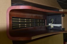
OOooh nice, this design is soooo simple its nice i see they used rubber bands to keep the folds from touching the magnets. if i remember correct they where not there in the first picture, the reason i said they where a bit to close. are they refurbished ?
looking out for some measurements
btw from how low should they be crossed ? since the rubber band are thicker then 2 mm, if your crossing around 400hz or so they could be thinner depending on the slope. with higher spl as a result
its nice i see they used rubber bands to keep the folds from touching the magnets. if i remember correct they where not there in the first picture, the reason i said they where a bit to close. are they refurbished ? looking out for some measurements
btw from how low should they be crossed ? since the rubber band are thicker then 2 mm, if your crossing around 400hz or so they could be thinner depending on the slope. with higher spl as a result
Last edited:
- Status
- This old topic is closed. If you want to reopen this topic, contact a moderator using the "Report Post" button.
- Home
- Loudspeakers
- Planars & Exotics
- Planar magnetic with central tweeter?