Would using AC be a conclusive test for arcing as compared to low current high voltage DC?
I have been using these transformers exclusively for over a year now without fail. It is my opinion that the issue should be put in perspective. for me, I am using perforated steel ESL's at 3kv, while someone who has built wire ESL's need greater bias voltage. That construction method conversely would require an increases in power requirements and also increase the likelihood of arcing.
I have been using these transformers exclusively for over a year now without fail. It is my opinion that the issue should be put in perspective. for me, I am using perforated steel ESL's at 3kv, while someone who has built wire ESL's need greater bias voltage. That construction method conversely would require an increases in power requirements and also increase the likelihood of arcing.
Would using AC be a conclusive test for arcing as compared to low current high voltage DC?
Yes. The AC test is appropriate since we are wanting to test for arcing inside the transformer due to voltage difference between the two 120V winding induced by the audio signal applied to the 6V windings. The DC bias voltage doesn't really come into play.
I have been using these transformers exclusively for over a year now without fail. It is my opinion that the issue should be put in perspective. for me, I am using perforated steel ESL's at 3kv, while someone who has built wire ESL's need greater bias voltage. That construction method conversely would require an increases in power requirements and also increase the likelihood of arcing.
In post #15 you mention using an ADCOM 535II. Great amp, btw.
With 50V supply rails, at most you would be driving your transformers with 35Vrms.
This result in 650Vrms between the bifilar 120V windings.
Glad to hear you haven't had any issues in 1+ year of use...a good data point.
As you stated, if people require increased voltage drive the likelihood of arcing increases.
The hope is that the wire arcing test I proposed will give some qualitative data to help define how much voltage the transformers can safely handle.
Excellence and quite useful qualitative data!
Another (non-topic) observation we have all noticed is that the ESL's drive with a lot less power from the amplifier than compared to my Magnaplanars, seemingly having a greater sensitivity....or is that because of the bias voltage acting as sort of a step-up pre-amp?
Regards,
Jerry/Doc
Another (non-topic) observation we have all noticed is that the ESL's drive with a lot less power from the amplifier than compared to my Magnaplanars, seemingly having a greater sensitivity....or is that because of the bias voltage acting as sort of a step-up pre-amp?
Regards,
Jerry/Doc
This is because ESL's are voltage devices and have a higher impedance at lower frequency's,the opposite of a dynamic driver in which are current driven devices.
Therefore the only time an ESL starts to make any significant demand on the amplifier is at the higher frequency's most notably starting about 5khz to 10khz depending on the transformation ratio and the systems total capacitance.
Well above the critical information band of 300hz to 3khz.
At the lower frequency's because of this higher impedance most amplifiers can swing almost there full power supply voltage with very little current demand.
Making it almost effortless for them to be played at a high level of SPL's.
It is when the transformers core goes into saturation at low frequency's that create havoc on an amplifier.
Or when the resonate frequency of the transformer is lowered in to the audio passband because of a high leakage inductance with the systems total capacitance.
This is the reasoning for the adding of some resistance.
Both situations create a heavy current demand on the amplifier.
So,as Bolserst had mentioned the can be some trade offs in that area.
The ultimate goal is to not have to add any extra resistance at all, as you know resistance is just a waste of precious power. he,he,he
jer")
Therefore the only time an ESL starts to make any significant demand on the amplifier is at the higher frequency's most notably starting about 5khz to 10khz depending on the transformation ratio and the systems total capacitance.
Well above the critical information band of 300hz to 3khz.
At the lower frequency's because of this higher impedance most amplifiers can swing almost there full power supply voltage with very little current demand.
Making it almost effortless for them to be played at a high level of SPL's.
It is when the transformers core goes into saturation at low frequency's that create havoc on an amplifier.
Or when the resonate frequency of the transformer is lowered in to the audio passband because of a high leakage inductance with the systems total capacitance.
This is the reasoning for the adding of some resistance.
Both situations create a heavy current demand on the amplifier.
So,as Bolserst had mentioned the can be some trade offs in that area.
The ultimate goal is to not have to add any extra resistance at all, as you know resistance is just a waste of precious power. he,he,he
jer
Last edited:
Antek Transformer...secondary arcing test
I completed the arcing tests between the wires of the bifilar wound 120V windings.
The short answer is that:
- for amplifiers < 150W/8ohm, the two transformer setup should work fine without arcing
- for amplifiers > 150W/8ohm, I would recommend using a series/parallel combination of 4 transformers.
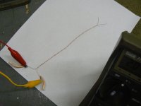
Attachment 1
Shows the preliminary arcing test setup with voltage applied between a twisted pair of the bifilar wound secondary wires.
The insulation withstood 1,000Vrms @ 1kHz for 5 minutes. But, I started noticing the distinct aroma of ozone.
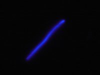
Attachment 2
Turning out the lights, you could see corona forming around the wire pair at any voltage above about 600Vrms.
Pic shows corona for 750Vrms @ 800Hz. Corona only forms in air.
High voltage transformers use oil or resin impregnation to avoid this problem.
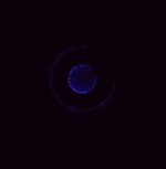
Attachment 3
Testing the whole secondary at 750Vrms, and the toroid gave a very pretty corona display. There is some resin or varnish applied to the secondary winding, but not enough to keep corona from forming. Sometime last night(after 2 days of constant 750Vrms) the insulation failed and arcing occured.
Over time, corona attacks the wire insulation and causes it to fail. It is a cumulative process. With this in mind, if I were to use these transformers for a hybrid ESL and planned to drive them with a 250W amplifier capable of 45-50Vrms output, I would use 4 of them instead of 2.
That being said, with the low peak/rms ratio of music it is highly possible that failure would not occur if only 2 transformers were used. But the possibility is there, and they are cheap enough that going from 2 to 4 isn't that painful to the pocket book. Also, with primaries in series-parallel, the core saturation capability is doubled allowing for lower crossover points if desired.
Alternatively, if your amplifier has good short circuit protection you could stick with the 2 transformer setup and just replace the set if you ever experience arcing.
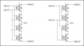
Attachment 4
Here are two possible methods for wiring the primaries of 4 transformers in series-parallel.
I can't think of an advantage of one over the other...perhaps somebody else can.
.
.
.
I completed the arcing tests between the wires of the bifilar wound 120V windings.
The short answer is that:
- for amplifiers < 150W/8ohm, the two transformer setup should work fine without arcing
- for amplifiers > 150W/8ohm, I would recommend using a series/parallel combination of 4 transformers.
Attachment 1
Shows the preliminary arcing test setup with voltage applied between a twisted pair of the bifilar wound secondary wires.
The insulation withstood 1,000Vrms @ 1kHz for 5 minutes. But, I started noticing the distinct aroma of ozone.
Attachment 2
Turning out the lights, you could see corona forming around the wire pair at any voltage above about 600Vrms.
Pic shows corona for 750Vrms @ 800Hz. Corona only forms in air.
High voltage transformers use oil or resin impregnation to avoid this problem.
Attachment 3
Testing the whole secondary at 750Vrms, and the toroid gave a very pretty corona display. There is some resin or varnish applied to the secondary winding, but not enough to keep corona from forming. Sometime last night(after 2 days of constant 750Vrms) the insulation failed and arcing occured.
Over time, corona attacks the wire insulation and causes it to fail. It is a cumulative process. With this in mind, if I were to use these transformers for a hybrid ESL and planned to drive them with a 250W amplifier capable of 45-50Vrms output, I would use 4 of them instead of 2.
That being said, with the low peak/rms ratio of music it is highly possible that failure would not occur if only 2 transformers were used. But the possibility is there, and they are cheap enough that going from 2 to 4 isn't that painful to the pocket book. Also, with primaries in series-parallel, the core saturation capability is doubled allowing for lower crossover points if desired.
Alternatively, if your amplifier has good short circuit protection you could stick with the 2 transformer setup and just replace the set if you ever experience arcing.
Attachment 4
Here are two possible methods for wiring the primaries of 4 transformers in series-parallel.
I can't think of an advantage of one over the other...perhaps somebody else can.
.
.
.
Attachments
There is no difference as far as input impedance or output voltage.Attachment4.
What is supposed to be different?
The impedance seen by the input voltage is identical for each arrangement.
Only the arrangement of series-parallel connections of the 8 primaries.
One may be physically more convenient or simpler to wire up than the other, but electrically they will perform the same.
Question:
If the corona is suppressed by potting, or whatever, does that change the reliability (no arcing) at high voltage operation?
Yes. If the transformer had been potted using a vacuum to ensure no air pockets remain, the corona would be suppressed and reliability would be improved.
Excellent! Thanks for the information. Having recommended these Antek trannys to others based on nothing more than a listening test, I'm relieved to know their limitations. I drove a pair of them to stator-slapping volume [momentarily] with 225 watt/ch amps so I figured they were OK. At $13 each, even 8 of them for a speaker pair is a bargain, though, and they sound great too.
Last edited:
This is good to know.
I have a little more info that may go along with this,
Yesterday, I finally got a chance to fire up my little panels again with my newly rebuilt power supply.
I was able too have resealed the stators on both panels and they both will sustain a bias voltage of 10Kv with no apparent leakage or noises from the panels.
When I hooked up the transformer I would start to hear some slight noise ( hisses and crackkling) very faint at voltages above about 7.5kv.
But no major arcing was visible or heard.
Then the noise got slightly more noticeable at voltages above 8kv of bias voltage but ceased at lower voltage about 6Kv to 5.2Kv.
I suspect that this is caused in the transformers that I am using, and, are of similar construction.
I only got to listen to the panels for a short period of time because of a failure of one of the FET's in the power supply.
I will have this fixed shortly.
I'm not sure what had caused this as of yet as I have ran the thing very heavily without any issues so far.
But ,It was ramping up indicating a large current draw and drop in the output voltage that would level out at around 5.2kv.
This does seem to indicate a failure of the insulation of the transformer and was intermittent at different voltages above 6.8Kv until it broke down sustaining a corona discharge somewhere inside although I could not see it.
So I didn't get much farther on this and I hope to have more on it soon.
jer
Last edited:
Thanks for the in depth research Bolserst...this information will prove valuable as to the limitations of those transformers, as well as to the max amp output that should be utilized. My Adcom is a mere 65watts and does a fantastic job pushing these panels!
Jer, I found several of my panels experiencing similar noises issues, while I believed it was an issue related to the power supply, I soon learned in a failure analysis tear down it was a HV leakage from my front stator to the center charge ring terminal through the double sided tape.
Good luck!!!
Jerry/Doc
Yes,Doc,that is normaly the case.
It was what I was scared of,but I had already tested the panels at 9 Kv to 10Kv prior to adding the transformers with no issues or noises.
But since the power supply had quit I couldn't recheck my panels again.
I am working on it now so I will be back with a confirmation shortly.
jer
It was what I was scared of,but I had already tested the panels at 9 Kv to 10Kv prior to adding the transformers with no issues or noises.
But since the power supply had quit I couldn't recheck my panels again.
I am working on it now so I will be back with a confirmation shortly.
jer
Thanks bolserst for the detailed analysis. Your ways and reports are always a delight.
Regarding the different series/parallel arrangements, perhaps a non-idealized circuit diagram (including all parasitic capacitance, inductances and wire resistance etc) will give more insight?
Regarding the different series/parallel arrangements, perhaps a non-idealized circuit diagram (including all parasitic capacitance, inductances and wire resistance etc) will give more insight?
I got my supply fixed and I just did some tests.
As it turns out the one panels is not quite up to par yet and had made a few more leakage points along the edge as expected.
The other panel I had spent much more time on it and it will sustain a 10Kv bias with no noises even with the two transformers hooked up.
Except on the initial charging of the diaphram and after everything as been charged and the voltages have equaled out it sits quietly all of the way up to 10kv except for any sudden large Bias voltage changes in which noise would be expected.
The panel that is working correctly has the original diagphram as when it was built in 2003 with the original formula Licron coating.
The diagphram on this panel has a very low tension and is why it takes it more time to stabilize as the bias voltage is raised.
The other panel is the one that I rebuilt tested and had blown up in my testing two years ago and had documented the rebuild in these threads.
I just need to reseal the edges with some Silicone as this seems to be the best stuff to use of all after all of the clear nail polished that I had used.
The nail polish works good but it take a lot of it and it thins more as it cures and the total cure time is very long as well.
One new strip on the older panel with some flowable silicone was all that it took so I will have to do the same to this one as well.
The transformers are the same as I had been using and I am think of getting some of those Antek's to give them a good go around to help confirm this study.
I have a primary turns count of 10 at the moment and this gives me a 1:254 transformation ratio.
And when I blew up the one panel I was running about double that with like 5 to 7 turns on the primary and a 50V to 60V signal into the transformer with my Crown DC300A amplifier.
Bringing my Stator voltage up around 25KV p-p out of the transformer before the edge of the panel gave out (the newer rebuild at the time).
As far as the bias goes I can now continue safe testing at 6.78Kv half of what my supply produces.
I have taken it to 10kv for a few short tests to see if any thing breaks down and it hasn't so far ,but this is just some preliminary test for now.
I will push it farther once I get some baseline data together and switch to an amplifier that is more capable as I am using my little cheapy Aiwa for right now.
As well as considering on a new panel build design for the much higher voltages as I am now pushing them 2 to 3 times what they were initially designed to do.
I can tell you this though is that I am getting aproximately 3db to 4db more sensitivity by increasing the bias voltage from about 6.5 (or so,nominal 6.78Kv) to 10kv as expected.
Sadly I don't have any measurement data from 2 years ago to see if any of the changes are relevant,But I assume they are.
My first successfull SPL measurement this morning was about 85.2db at 1 meter with a pink noise signal feeding a 10 turn primary (1:254) and a 1 ohm resistor in series with the primary at a 10kv bias.
With out the resistor this figure would be a bit higher.
Also the lows at 80hz and highs at 12khz were cut but 12db because the amp can't handle it,so this was the most this amp can do before it shuts down.
But this is about 102db 5 inches from the diagphram.
I didn't want to go of topic But I figured I would give the heads up on my findings and test setup and if I do get some Anteks or run into any other transformer issues I will mention them here.
Thanks !!
jer
Last edited:
Regarding the different series/parallel arrangements, perhaps a non-idealized circuit diagram (including all parasitic capacitance, inductances and wire resistance etc) will give more insight?
You are right of course...I really should put together a SPICE model of the 4 transformer arrangement with all parasitics modeled to see if one arrangement has any advantages as far as HF bandwidth. I had been thinking that since all 8 of the primaries are pretty much at the same voltage potential when compared to the HV on the secondary windings, the connection arrangement of the primaries would have little if any affect on the HF bandwidth.
But, we all know what happens when you get to thinking too much
Last edited:
I was working on my transformer configuration yesterday.
I used my cheapy amp because it gives me a sense of reference for an overload condition that is consistent.
My cores I believe have bifilar 120v windings as well.
With 10 primary turns on each of the two cores and and the 4 120v windings in series as normal.
This gives me a 1:256 transformation ratio so it is quite high,But again I am running smaller panels and the panels capacitance is nil compared to that of the transformers capacitance.
So this test makes no difference if the panels are connected or not.
What I have found is that I could not go past 2Khz with a 10V peak signal without the amp shutting down.
When I tried using 4 cores using only one 120V winding on each core in the same configuration of a 1:256 transformation ratio, I was able to sail on past the 2Khz barrier to 20khz wit a 10V peak input signal with no overload or shutdown,and even to 20Vpeak at 20Khz with my cheapy amp.
This is a very significant improvement.
I have not been able to document any higher voltages because my 10X scope probe is broke and the scope graticule only goes to 20v p-p.
But I was actually able to now use my cheapy amp at a reasonably loud volume without it being so sensitive to overload and shutting down on high peaks (as much).
It was quite loud for pleasure listening at this point with no interuptions.
I Measured 102db at 1 meter with test tones before the amp shutdown at maximum output.
This is around a 16db improvement over my very first measurement in post #33.
I haven't yet measured the capacitance of the new configuration to compare the difference, yet.
But, I do think that it is safe to say that one should seek using transformers with a single 230V winding than using one with two 115V or 120V windings or use 4 cores of the lesser for better performance than using two cores.
Possibly one such as the Farnell transformer that CharlieM had mentioned.
Gotta Love R&D !!!!

jer
I used my cheapy amp because it gives me a sense of reference for an overload condition that is consistent.
My cores I believe have bifilar 120v windings as well.
With 10 primary turns on each of the two cores and and the 4 120v windings in series as normal.
This gives me a 1:256 transformation ratio so it is quite high,But again I am running smaller panels and the panels capacitance is nil compared to that of the transformers capacitance.
So this test makes no difference if the panels are connected or not.
What I have found is that I could not go past 2Khz with a 10V peak signal without the amp shutting down.
When I tried using 4 cores using only one 120V winding on each core in the same configuration of a 1:256 transformation ratio, I was able to sail on past the 2Khz barrier to 20khz wit a 10V peak input signal with no overload or shutdown,and even to 20Vpeak at 20Khz with my cheapy amp.
This is a very significant improvement.
I have not been able to document any higher voltages because my 10X scope probe is broke and the scope graticule only goes to 20v p-p.
But I was actually able to now use my cheapy amp at a reasonably loud volume without it being so sensitive to overload and shutting down on high peaks (as much).
It was quite loud for pleasure listening at this point with no interuptions.
I Measured 102db at 1 meter with test tones before the amp shutdown at maximum output.
This is around a 16db improvement over my very first measurement in post #33.
I haven't yet measured the capacitance of the new configuration to compare the difference, yet.
But, I do think that it is safe to say that one should seek using transformers with a single 230V winding than using one with two 115V or 120V windings or use 4 cores of the lesser for better performance than using two cores.
Possibly one such as the Farnell transformer that CharlieM had mentioned.
Gotta Love R&D !!!!
jer
Last edited:
Hello,
a toroidal trafo company could make me (for example) a step up transformers (2x 6V / 2x 115V) that have 70 turns on PRI, a core area of 10,5cm2. Could I excpect something like 10V/20V saturation point at 50Hz with such trafo depending on the connecting style? I looked at the formula found here that one can use to estimate the saturation point, but did not actually quite master it.
I could also opt get an electrostatic shield between the pri and sec to the trafos. Would this be beneficial? Verwaal (http://home.kpn.nl/verwa255/esl/ESL_English_2011.pdf) states on page 118-119 that primary's capacitance should be connected to the center tap of the secondary. So if the transformer has an electrostatic shield, should one connect it to the center tap, and would this be actually a good thing to have (widens the bandwidth?)? I have got the impression that the electrostatic shield decreases the parasitic capacitance between the pri and sec, so I would prima facie think that it is a good thing...
Also something regarding the leakage inductance of the transformer... My panels have approx 2.8nF capacitance. I tried to calculate the highest possible secondary leakage inductance that would put the LC resonant circuit's frequency to audio band with calculators found on the net, but this is not propably the correct way (the resonant frequencies were near MHz)? I have understood that there is also the the second LC from the secondary windings parallel capacitance that forms an LC circuit with the leakage inductance, but this might not be problem if there are several secondaries put into series, so the main LC that we should worry is the leakage inductance and the panel's load? Anyway what would be a general quide line with 2.8nF panel regarding the leakage inductance, how high it should/can be without problems in HF response?
Thanks in advance!
Regards,
Legis
Last edited:
Correct. With 70 primary turns on 10.5cm^2 area core, saturation onset point would be about 20Vrms for 50Hz.a toroidal trafo company could make me (for example) a step up transformers (2x 6V / 2x 115V) that have 70 turns on PRI, a core area of 10,5cm2. Could I excpect something like 10V/20V saturation point at 50Hz with such trafo depending on the connecting style?
The statement basically means that rather than winding all of the secondary in one section, it is best to wind the transformer with 1/2 of the secondary one either side of the primary. Then the ends of the two secondary halves closest to the primary should be connected together as the center tap. This arrangement minimized primary-to-secondary capacitance. If this winding arrangment is used, adding electrostatic shielding would be of little benefit since the potential difference between the primary and adjacent secondary layers is relatively low.I could also opt get an electrostatic shield between the pri and sec to the trafos. Would this be beneficial? Verwaal (http://home.kpn.nl/verwa255/esl/ESL_English_2011.pdf) states on page 118-119 that primary's capacitance should be connected to the center tap of the secondary.
That is pretty high panel capacitance. I would say you probably would want to keep the effective primary leakage inductance below 4uH - 6uH depending on the level of winding capacitance. When calculating upper bandwidth limit, don't forget you need to reflect the leakage inductance and panel capacitance to the same side of the transformer before doing the resonance calculation. For example, 4uH on the primary becomes 22mH when reflected to the secondary thru a 75:1 step-up transformer. Don't forget to include the transformer winding capacitance (810pF for the Plitron) which brings total secondary capacitive load to 3.6nF.Also something regarding the leakage inductance of the transformer... My panels have approx 2.8nF capacitance....Anyway what would be a general quide line with 2.8nF panel regarding the leakage inductance, how high it should/can be without problems in HF response?
Then you can calculate the resonance frequency:
F=1/(2*pi*sqrt(L*C)) = 17.7kHz
You can also play around with the transformer-ESL modeler spreadsheets I posted which had some examples with the Plitron transformer.
http://www.diyaudio.com/forums/plan...101-electronics-challenged-2.html#post2555863
Correct. With 70 primary turns on 10.5cm^2 area core, saturation onset point would be about 20Vrms for 50Hz.
The statement basically means that rather than winding all of the secondary in one section, it is best to wind the transformer with 1/2 of the secondary one either side of the primary. Then the ends of the two secondary halves closest to the primary should be connected together as the center tap. This arrangement minimized primary-to-secondary capacitance. If this winding arrangment is used, adding electrostatic shielding would be of little benefit since the potential difference between the primary and adjacent secondary layers is relatively low.
That is pretty high panel capacitance. I would say you probably would want to keep the effective primary leakage inductance below 4uH - 6uH depending on the level of winding capacitance. When calculating upper bandwidth limit, don't forget you need to reflect the leakage inductance and panel capacitance to the same side of the transformer before doing the resonance calculation. For example, 4uH on the primary becomes 22mH when reflected to the secondary thru a 75:1 step-up transformer. Don't forget to include the transformer winding capacitance (810pF for the Plitron) which brings total secondary capacitive load to 3.6nF.
Then you can calculate the resonance frequency:
F=1/(2*pi*sqrt(L*C)) = 17.7kHz
You can also play around with the transformer-ESL modeler spreadsheets I posted which had some examples with the Plitron transformer.
http://www.diyaudio.com/forums/plan...101-electronics-challenged-2.html#post2555863
Hi bolserst, thanks for the reply. Plitron's data might not be accurate as it does not resonate at audioband with my stats, Verwaal also stated that Plitron's measured resonance was ~10kHz upper than simulated based on the data.
But if i were to connect the 6 Anteks like we discussed via email, what happens to the resonant frequency, does it get up or down?
I read between the lines, that the electrostatic shield in beneficial, or at least it is not harmful in any case? I get if for the same price so it might be better to just get it.
-Legis
Plitron's data might not be accurate as it does not resonate at audioband with my stats, Verwaal also stated that Plitron's measured resonance was ~10kHz upper than simulated based on the data.
But if i were to connect the 6 Anteks like we discussed via email, what happens to the resonant frequency, does it get up or down?
I read between the lines, that the electrostatic shield in beneficial, or at least it is not harmful in any case? I get if for the same price so it might be better to just get it.
How did you determine the resonance point of your stats? In most cases you will not see a pronounced peak in the frequency response unless you use no damping resistor, your panels are flat, and you are measuring on-axis. The easiest way to determine it is to measure the impedance and look for the zero phase crossing point at the top of the audio band where the impedance reaches a minimum. Note that even with voltage drive to the stators rolling off before 20Khz, the measured SPL may still be relatively flat because directivity gain of large panels boosts high frequencies.
Adding more transformers in parallel/series will result in resonance frequency going down.
Even if the added transformers were perfect, the increased step-up ratio would increase the reflected leakage inductance or load capacitance.
Shielding is not harmful, but it may increase the distance separating the primary and secondary which would increase leakage inductance. For power transformers this is not a big concern, but if used for ESL step-up transformers driving a large capacitive load it might be.
Attachments
I have been going through some data on cores lately and you had stated that the Core Area of the Antek AN-0506 was about .7 square inches.
I was wondering if you could post the O.D. x I.D. x HT dimensions of the bare core in mm.
This is so that I can have a more accurate approximation in my comparisons of a few designs that I am tossing about.
Thanks !!
jer
I was wondering if you could post the O.D. x I.D. x HT dimensions of the bare core in mm.
This is so that I can have a more accurate approximation in my comparisons of a few designs that I am tossing about.
Thanks !!
jer
- Status
- This old topic is closed. If you want to reopen this topic, contact a moderator using the "Report Post" button.
- Home
- Loudspeakers
- Planars & Exotics
- Antek Toroidal power transformer for Step-up, Measurements (part 1/2)