After Calvin brought them to our attention, many folks have used small toroidal power transformers for step-up transformers in hybrid ESL systems.
http://www.diyaudio.com/forums/planars-exotics/68573-new-trannies.html
CharlieM and others have had good luck with the Antek AN-0506, 50VA 2x 115v/2x6v transformers.
http://www.diyaudio.com/forums/plan...know-us-source-esl-toroids-6.html#post2195620
However, there was always a concern about potential for internal arcing between the two 115V windings since the exact construction was not known.
Measurement of parasitics
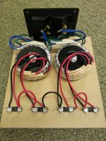
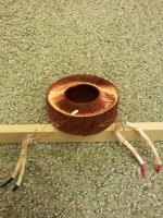
Two transformers were hooked up in the usual manner with all 6v volt windings in parallel and all the 115V windings in series. See attachment .
Step-up ratio = 1:74
Leakage inductance = 2.5uH (all leakage reflected to primary)
Secondary winding capacitance = 1000pF - 1300pF (depends on series order the 115V winding )
So, driving a ~ 1000pF ESL panel like CharlieM’s would be no problem whatsoever.
In fact, even a 2000pF load would not drop the HF bandwidth below 20kHz.
Measurement of Power handling
With 0.5ohm current sensing resistor in series with primaries, I looked for the point at which the current spikes exceeded twice the RMS value…indicating the onset of core saturation.
100Hz = 10Vrms
200Hz = 20Vrms
400Hz = 40Vrms.
So, a hybrid crossed at 400Hz could be driven with a 200W/8ohm amplifier without any chance of core saturation. Adding resistance in series with primary of 1ohm – 2ohm would increase the power handling capability.
Calculation of Power handling
Just to check if the math works….
Primary turns = 44
Core size = 1” x 0.7” = 0.7 in^2
Using the formulas provided in the post below, we can calculate that at 400Hz the onset of saturation would occur around 42Vrms.
That’s pretty good agreement with measurements.
http://www.diyaudio.com/forums/planars-exotics/161485-step-up-transformer-design-4.html#post2096503
http://www.diyaudio.com/forums/planars-exotics/68573-new-trannies.html
CharlieM and others have had good luck with the Antek AN-0506, 50VA 2x 115v/2x6v transformers.
http://www.diyaudio.com/forums/plan...know-us-source-esl-toroids-6.html#post2195620
However, there was always a concern about potential for internal arcing between the two 115V windings since the exact construction was not known.
Measurement of parasitics
Two transformers were hooked up in the usual manner with all 6v volt windings in parallel and all the 115V windings in series. See attachment .
Step-up ratio = 1:74
Leakage inductance = 2.5uH (all leakage reflected to primary)
Secondary winding capacitance = 1000pF - 1300pF (depends on series order the 115V winding )
So, driving a ~ 1000pF ESL panel like CharlieM’s would be no problem whatsoever.
In fact, even a 2000pF load would not drop the HF bandwidth below 20kHz.
Measurement of Power handling
With 0.5ohm current sensing resistor in series with primaries, I looked for the point at which the current spikes exceeded twice the RMS value…indicating the onset of core saturation.
100Hz = 10Vrms
200Hz = 20Vrms
400Hz = 40Vrms.
So, a hybrid crossed at 400Hz could be driven with a 200W/8ohm amplifier without any chance of core saturation. Adding resistance in series with primary of 1ohm – 2ohm would increase the power handling capability.
Calculation of Power handling
Just to check if the math works….
Primary turns = 44
Core size = 1” x 0.7” = 0.7 in^2
Using the formulas provided in the post below, we can calculate that at 400Hz the onset of saturation would occur around 42Vrms.
That’s pretty good agreement with measurements.
http://www.diyaudio.com/forums/planars-exotics/161485-step-up-transformer-design-4.html#post2096503
Attachments
Antek Toroidal power transformer for Step-up, De-construction (part 2/2)
Ok, so now on to the elephant in the room…
What about the potential for arcing between the 115V windings?
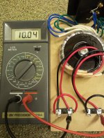
The first thing I did was measure the capacitance between the two 115V windings with ends shorted as shown in attachment (1).
This would give an idea of how physically close the two windings are to each other.
If they are separated by some insulation, the capacitance would be less. If not…more.
Measurement showed 10nF = 10,000pF.
Hmmmm…this says that if there is insulation between them, there isn’t much.
So, nothing left but to unwind the transformer and see what is what.
Attachment (2)
Outer insulation tape removed revealing the two 44 turn primaries.
Attachment (3)
Primaries removed revealing primary-secondary insulation layer.
Attachment (4)
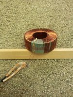
Insulation layer was made of up 6 layers of 2mil polyester….undeneath, the secondaries.
This does NOT look good, seeing both the black wires leading off together to the start of the winding.
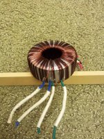
Attachment (5)
Unwinding the secondaries revealed that the two 115V windings are wound at the same time next to each other, so bifilar wound.
No insulation between them other than the enamel on the wire.
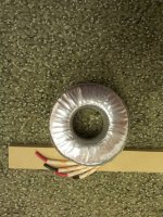
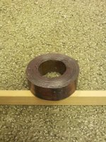
Attachment (6)
The raw core.
With bifilar 115V windings hooked in series and 40Vrms applied to the primaries the output voltage would be 40Vrms x 37 = 1480Vrms.
The voltage between the two secondaries will be half that, or about 750Vrms.
Now the question is, can the enamel insulation stand up to this voltage?
I think the answer is that it depends on the exact formulation of the insulation and its thickness.
So, I'm not sure if we really know any more than we did before concerning whether these transformers will be realiable when used used as ESL step-ups.
But, I am $13 poorer")
.
Ok, so now on to the elephant in the room…
What about the potential for arcing between the 115V windings?
The first thing I did was measure the capacitance between the two 115V windings with ends shorted as shown in attachment (1).
This would give an idea of how physically close the two windings are to each other.
If they are separated by some insulation, the capacitance would be less. If not…more.
Measurement showed 10nF = 10,000pF.
Hmmmm…this says that if there is insulation between them, there isn’t much.
So, nothing left but to unwind the transformer and see what is what.
Attachment (2)
Outer insulation tape removed revealing the two 44 turn primaries.
Attachment (3)
Primaries removed revealing primary-secondary insulation layer.
Attachment (4)
Insulation layer was made of up 6 layers of 2mil polyester….undeneath, the secondaries.
This does NOT look good, seeing both the black wires leading off together to the start of the winding.
Attachment (5)
Unwinding the secondaries revealed that the two 115V windings are wound at the same time next to each other, so bifilar wound.
No insulation between them other than the enamel on the wire.
Attachment (6)
The raw core.
With bifilar 115V windings hooked in series and 40Vrms applied to the primaries the output voltage would be 40Vrms x 37 = 1480Vrms.
The voltage between the two secondaries will be half that, or about 750Vrms.
Now the question is, can the enamel insulation stand up to this voltage?
I think the answer is that it depends on the exact formulation of the insulation and its thickness.
So, I'm not sure if we really know any more than we did before concerning whether these transformers will be realiable when used used as ESL step-ups.
But, I am $13 poorer
.
Attachments
Very Nice Report Bolserst !!!
It is good too now know the characteristics of that transformer.
The parasitic capacitance seems to be quite on the highside ,about 60% to 100% higher than the cores that I have any how ,But at least they do work well.
I have been planning on doing this same thing with my cores as well.
Are you going to add some insulation to try and see how far you can bring that residual capacitance down and rewind it?
I plan on doing this with my cores as the panels that I am messing with won't be much more than 500pf right now.
So all that extra transformer capacitance becomes a waste of amplifier power.
In my extreme tests I didn't experience any problems of arcing between the windings that I know of at 25Kv P-P.
Except one time I had a snap or two between two stacked cores as the air was ionizing between them and they where separated by a 1/4" gap.
I had no shorted or open windings and had no change in the measurement of the transformation ratio.
I too have noticed different values of capacitance depending on how the windings were connected and the added windings that are unused make it worse.
How did you determine the capacitance of your windings?
Did you use a capacitance meter or the resonate method?
I now have a new meter and it measures capacitance so I have tried both methods and I seem to almost get the same result using both methods when I can get an accurate reading from my frequency counter ( as it needs some work too,it has been not working well).
As it also depends on the wiring configuration,it just makes it more confusing.
But still consistent with last years measurements.
I get about 400pf to 600pf,but with the meter I have measured as low as 300pf and as high as 1100pf in some combinations with the extra windings just connected to them self.
It is good to see that the leakage inductance is low and the photo's prove why.
Because I would like to have a little more low end response I am debating on winding a new secondary winding with some Kynar covered wire after I strip off all of the existing secondary windings.
The existing primary windings would allow me to run 50Vrms to 60Vrms at 30hz or cut them in half and settle for 60hz for a lowest frequency as this would cut down on the secondary wire mileage. he,he
Hmmm....................
I think that as long as the current is flowing through the wire the voltage gets distributed evenly across each winding, so that the stress between each successive winding is much less than if the transformer was open and had no load.
Yes the whole thing is energized with the bias voltage ,But ,The whole thing is at the same potential.
It was only in this type of no load condition that I had a couple of snapping incidences.
I could/did not see the arc so I don't know where they were or originated from,nor did I see any holes burned in the heavy mylar tape covering the core.
Thanks for the info and your sacrifice of that transformer !!!!
jer
Last edited:
I fond this info 3years ago whin i got a pr of SoundLab A1....the two tranfourmers in the A1 were setup just like the Acoustats...the high fre. tranfourmer was a toroidal.
Dr west give some insite on the toroidal tranfourmer....
When I removed one of the backplates to see how the equalization was accomplished, I found that the LOWs were adjusted by selecting one of four different taps on the primary of the bass transformer, and the MIDs were controlled by placing different values of inductance in series with the primary of the bass transformer. The "0" setting used 5mH and the "+3" setting connected the bass transformer directly to the input (no inductor). The high-frequency toroidal transformer was connected to the inputs through a single-pole high-pass filter where the series C=48uF (two 24uF polyproylenes in parallel) and the shunt R=5 ohms (four 5 ohm 10W in series/parallel), for a corner frequency of 660Hz. This explained a lot, since the presence of the 5 ohm resistor meant that the overall impedance could be no higher than 5 ohms above the corner frequency, so I knew my measurements were not in error.
When I asked Roger West why he used such a low impedance, he explained that,
"The toroids require the lower impedance coupling network (48ufds, 5 ohms) to prevent the toroids from being saturated by low-frequency energy feeding back from the high-voltage mixer. The lower impedance reflected to the secondary of the toroid reduces the low-frequency energy coming from the secondary of the low-frequency transformer. Our conventional high-frequency transformer doesn't require the lower impedance, but it doesn't have the benefits of the toroid."
Ok, so now on to the elephant in the room…
What about the potential for arcing between the 115V windings?
With bifilar 115V windings hooked in series and 40Vrms applied to the primaries the output voltage would be 40Vrms x 37 = 1480Vrms.
The voltage between the two secondaries will be half that, or about 750Vrms.
Now the question is, can the enamel insulation stand up to this voltage?
I think the answer is that it depends on the exact formulation of the insulation and its thickness.
So, I'm not sure if we really know any more than we did before concerning whether these transformers will be realiable when used used as ESL step-ups.
But, I am $13 poorer
.
Great report! I wish I had something to add but, unfortunately, I too don't know how these trannys would hold up over time. I'm actually still using the Farnell 50VA 230v/2x6v trannys to drive my panels, but I did try out the Anteks for a few hours-- just long enough to verify their sound-- and I did drive them to painful volume for a brief period and nothing smoked.
Another forum member (Jerry) is using the Anteks and reporting good results so far but I don't know what kind of power he's feeding them. Maybe Jerry will chime in and shed some light on that.
Bolserst, thanks for the info and keep us posted on anything else you find out-- because, as you know, I'm calling out the Anteks on my web page because the Farnell's I like are no longer available in the US and the Anteks are the only alternatives I know of, short of the $$$ Plitrons. In any case, I wouldn't want to continue recommending them if anyone reports a failure.
Last edited:
You can measure leakage inductance fairly easily by hooking up an inductance meter to the primary and shorting the secondary windings.How did you determine the capacitance of your windings?
Did you use a capacitance meter or the resonate method?
But, I don't know of an easy way to directly measure the winding capacitance.
The best way I have found was documented in a thread here:
http://www.diyaudio.com/forums/plan...ruct-cube-louver-acoustat-14.html#post2181730
It is kinda cool because you determine both the winding capacitance and the leakage inductance at the same time.
I usually plot curves for 3 or 4 different load capacitances.
If all the measurements were done well, the curves will all cross at one point on the plot indicating the leakage inductance and winding capacitance.
See attached plot for a sample of one set of the Antek measurements.
Leakage inductance is proportional to the square of the primary turns and inversely proportional to the length of the winding.It is good to see that the leakage inductance is low and the photo's prove why.
So having only 44 primary turns is good. And having complete coverage of the toroidal core circumference is a good thing.
See middle of this post for leakage inductance formula.
http://www.diyaudio.com/forums/planars-exotics/161485-step-up-transformer-design-12.html#post2122717
.
Attachments
Perhaps the other one could be sacrificed for some empirical data gathering? Or in other words turn up the input voltage until it does arc
Maybe I'll setup a donation fund to pay for the sacrificial test
Seriously though, I may do that early next year if I can find the time.
It would need to be a high frequency (1kHz maybe) long duration test, increasing voltage slightly every week if we really want to know what it can reliably handle.
"The toroids require the lower impedance coupling network (48ufds, 5 ohms) to prevent the toroids from being saturated by low-frequency energy feeding back from the high-voltage mixer. The lower impedance reflected to the secondary of the toroid reduces the low-frequency energy coming from the secondary of the low-frequency transformer. Our conventional high-frequency transformer doesn't require the lower impedance, but it doesn't have the benefits of the toroid."
Something else that Soundlab "borrowed" from Acoustat.
This technique was first introduced in the C-mod.
Highly recommended.
Maybe I'll setup a donation fund to pay for the sacrificial test
Seriously though, I may do that early next year if I can find the time.
It would need to be a high frequency (1kHz maybe) long duration test, increasing voltage slightly every week if we really want to know what it can reliably handle.
Hey, I'm throw in a few bucks for the cause... just PM me an address!
Yes ,Bolserst,those are the the same links to the methods I use I remember them quite well.
I do have a capacitance meter but not an inductance meter yet as it is on my list of things to have to build next.
I was referring to the primary having very good coverage of the core as that makes a big difference in itself.
Again Thanks !!!
jer
I do have a capacitance meter but not an inductance meter yet as it is on my list of things to have to build next.
I was referring to the primary having very good coverage of the core as that makes a big difference in itself.
Again Thanks !!!
jer
AnTek has another transformer with similar specs but rated at 100VA and a shield between the primary and secondary. Also has an external magnetic shield. This might be a better choice. Only about $10 more.
Antek - AS-1206
Antek - AS-1206
Hello All,
Well I thought the Antec transformers were a great buy...so I bought 20 of them (for myself and friends ESL builds). I am using them nearly everyday with no alterations and have not experienced any signs of arcing.
I have not measured the capacitance of my panels, however they measure 15"x48". I have essentially deviated from the 1ohm/10w resistor to 8ohm/20w, some will argue there would be an appreciable loss of high frequencies, but this was not my experience.
I am essentially using a 3kv bias power supply and my 6um myar is stretched to just over 2.5% elongation.
My Amp is an ADCOM GFA-535II. got it on EBAY for 100.00, it sounds fantastic, however I use it like a rented-donkey!....If it smokes i'll get a bigger one....
In practice it has been working flawless and the only arcing we had to deal with occurred between the XLR connectors if the heat shrink was not on properly (nail polish resolved that issue). Currently several of my friends now have there set-up using those trannies a over time a better longitudinal study can be observed.
I believe these were an excellent find, thanks again Charlie!
Best Regards and Happy Holidays,
Jerry
Bolserst,
question, after your analysis of the Antec AS-0506, what if anything would you change?
And what affect if any would it have on either sound quality or Amplifier load resistance?
The things I would change are:
1) Increase power handling capability by either using more primary turns, or a larger core.
2) Wind the secondary with insulation tape between each layer. This would not only avoid any potential arcing issues, but also cut the winding capacitance by 50% - 75%.
3) In general I like to minimize winding capacitance at the expense of increased leakage inductance. For the same HF bandwidth limit, a design with lower capacitance(but higher leakage inductance) allows you to increase the value of the series damping resistance for the same HF roll off. This makes the HF load impedance higher in magnitude and the phase more resistive, both of which makes the load easier for amplifiers to drive. It also makes "tuning" of the series resistance less critical.
Perhaps the other one could be sacrificed for some empirical data gathering? Or in other words turn up the input voltage until it does arc
After thinking some more about the sacrificial test, it struck me that I can get the information we are after without having to destroy another transformer. What we want to know is at what voltage the insulation between two adjacent wires of the secondary will fail. I have the wire I unwound from the first transformer, so all I need to do is twist two wires together for a foot or so and then apply the AC voltage between them. Increase the voltage and wait for the fireworks.
Should probably have some time to set this up next week.
Will probably set up a dozen or so twisted pairs to see if they all fail at similar voltages.
- Status
- This old topic is closed. If you want to reopen this topic, contact a moderator using the "Report Post" button.
- Home
- Loudspeakers
- Planars & Exotics
- Antek Toroidal power transformer for Step-up, Measurements (part 1/2)