This will sound dumb... when you say leaking... what do you mean? Frankly I am quite confident as to why the humming is occuring... the whole damn stator is bent... and not in a good way! It was metal that I knew I probably should not try but I thought what the hell I don't have to cut it so I gave it a go. So I am assuming the mylar is in constant contact with the metal. Would this cause the humming-whine sound? I saw no sparking.
I need to go over my electronics setup with you geraldfryjr... I just have been busy. Maybe I screwed up on reading the schematic of Charlies... but it seems simple enough.
I also want to tell everyone this - DO NOT TRY LINKED METAL WITH 1/16TH 3m FOAM TAPE. It does not work. The reason is the tape going on the metal does not form a good edge to keep the appropriate spacing. The metal (it is not the same as expanded metal) consistently would touch the mylar. It might work with hard plastic spacers - this I don't know. My god did I waste money spraying can after can on that linked metal!
I am starting to see the many advantages (I don't know the disadvantages) of wire stators. Doing a couple stators by spraying I can see. Doing more then a few - powder coating with maybe a couple of sprays of something... or using wire, seems to be the only way to approach any reasonable efficiency. I read that one person on here has wiring a stator with a device down to a 7 minute procedure... and the magnet wire is insulated... sounds good to me. Can after can... guess it works but kind of insane.
I just hate doing something - even a few - that is so inefficient. Ugh.
Last edited:
I if it is a 60Hz humming sound then it could be the connections to your bias supply like I had mentioned.
If it is a screach type of whining the panel could be leaking high voltage some where.
If this is the case you may not be able to see it even with the lights off.
If it seems that the diagrpharm is oscillating this can be from if the panels are badly bent and is touching the diagphram or that there is not enough tension on the diagphram.
But there is quite a bit of room for tolerance there, maybe around 10% to 20% of the spacing thickness but no more than 20% I have found.
I can put a pretty good bend on my panels with no issues.
you had said that the width of your panel is 12" and a a 1/16" D/S is much to small for a panel of this width remember the 100:1 (Diagphram width to spacing) rule as a minimum.
At first I had a hard time getting enough tension on my 8.5" wide panels and had to get the heat gun out a few times until a got it right.
I ended up going with a .09375" spacers on those although I did get them to work with the .065" to .072" that I first used.
Are your panels flat or is this the curved ones that you are trying?
The only time you can lower this ratio is for narrower panels but not by much to maybe 70:1 if you are lucky and for high frequency's only and headphone drivers with a lowered bias voltage as well.
Try backing the bias voltage down and see if it stabilizes .
Jer")
P.S. I will PM you my Contact number as I had promised.
If it is a screach type of whining the panel could be leaking high voltage some where.
If this is the case you may not be able to see it even with the lights off.
If it seems that the diagrpharm is oscillating this can be from if the panels are badly bent and is touching the diagphram or that there is not enough tension on the diagphram.
But there is quite a bit of room for tolerance there, maybe around 10% to 20% of the spacing thickness but no more than 20% I have found.
I can put a pretty good bend on my panels with no issues.
you had said that the width of your panel is 12" and a a 1/16" D/S is much to small for a panel of this width remember the 100:1 (Diagphram width to spacing) rule as a minimum.
At first I had a hard time getting enough tension on my 8.5" wide panels and had to get the heat gun out a few times until a got it right.
I ended up going with a .09375" spacers on those although I did get them to work with the .065" to .072" that I first used.
Are your panels flat or is this the curved ones that you are trying?
The only time you can lower this ratio is for narrower panels but not by much to maybe 70:1 if you are lucky and for high frequency's only and headphone drivers with a lowered bias voltage as well.
Try backing the bias voltage down and see if it stabilizes .
Jer
P.S. I will PM you my Contact number as I had promised.
Thanks for the PM... will give you a call. The 12x24 or flat and currently have a 1/6th spacing. They are bending from top to bottom. These are not a big deal to tear apart and redo as I have merely a weak foam tape on them. They are powder coated. I think the best way to describe the sound is whining and whirring and staticy. The frequency on the whining changes with my modulation of my bias if that tells you anything. I am using an expensive 10kv very thin wire with a heavy clear coating... spec'd for 10kv max. Surprised how thin the inner wire is. I am connecting it to the mylar via the copper lead tape stuff. Connecting this wire to the pins off of the emco may be the problem... it is meant to be surface mounted I think... what do I know... the pins are not long though. I have them sticking through the perf and did my best solder attempt. By the way those Emco new - I had them quote me some... $200 - 250.00 Ouch!
Since I have burned up one of my little panels I have been working on the coating issues today.
As most should know, It was made of powder coated aluminium wire mesh and seemed to have developed some cracks in the coating through the years.
In order to refurbish them I used many coats of clear acrylic to reseal them.
But still another bad spot had developed and I failed to maintain it.
This ultimately burned it really bad.
This I already had posted in another thread and I will pursue the problem I had with Powder coating at a later date.
So it is time to build some new panels.
In the photos that I am presenting show some of the issues I had, such as cracks, bubbles and inconsistent thicknesses in the coating layer.
Although it worked quite well (for awhile) it just wasn't up to the higher voltages that I have been aiming for as the other panel did hold up.
I do believe that it could have been avoided had I addressed the problem promptly.
On my first panels I had used some enamel spray paint but it had a white pigment in it and these worked good as well.
But, The maximum voltages on those couldn't get very much higher than half of the normal operating voltages of the panel that had failed.
Those still work but I stopped using them as well for obvious reasons of suffering performance.
The coating procedure I have now seems to be very promising and has approached withholding the voltages of the refurbished powder coated panel that had failed and surpassed those of the panel that I had used with the white pigment ( titanium dioxide) in some preliminary breakdown voltage tests.
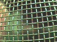
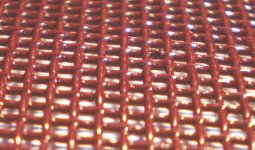
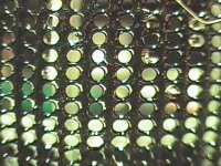
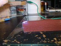
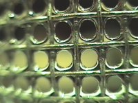
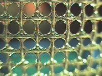
Starting a wire mesh thickness of approximately 22.5 mil of thickness,I built up the coating to a total thickness 31.5 mil with the mesh using an etching type prime as a base and then a black enamel to seal it with and then a heavy coat of a red oxide primer that has no pigment and has a heavy content of Talc.
I then finished it off with some 2X Clear acrylic enamel.
This gave me an estimated coating thickness of 4.5mil.
I am not sure if the primer coatings have any significant value the bond to the wire mesh are not but Talc is a very good insulator and has a high Dielectric constant as well.
I will make a sample with just clear acrylic on it to try also.
As the weather is getting better I will make a sample with some sprayed on polyurethane too.
It may prove to be less prone to cracking during the flexing of the screen in the construction process from what I have been reading about the differences between the two materials.
I suspect the acrylic will be the better insulator in this case, But I shall find out very soon.
But, I have found out first hand it is not wise to coat one with the other.
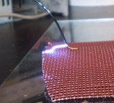
With the output of my supply connected to the screen I used the ground lead as my probe so that I could move it if need without the risk of getting shocked.
With the ground wire laying on and touching the coating I was able to set the supply as high as 5.2kv to 5.5kv without any arcing at all.
Above this some spots even withheld my half way point of 6.78Kv with the probe held approximately 1/8" to 1/4" above the sample and when it did arc the discharge point of weakness was at least a 1cm away from where the point of the probe was being held above the sample.
I had even found a few areas were this distance was much greater.
This has shown me that the Dielectric strength of this coating is in the order of 1.5kv per mil.
It is about what I had figured and was hoping for,Very impressive indeed!!!
I gave the sample another generous coating of some regular clear and I will test it some more after it has had some time to fully cure.
I used the regular stuff this time because it was what I had readily available at the time and the fact that is thinner.
This allowed to it to flow better giving less of a chance to allow any holes to get plugged up.
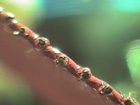
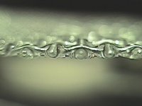
The closeup photo of the sample laying on a piece paper was taking after the latest coat was applied and notice how much more consistent the thicknesses are compared to the Powder coated stator (in Black).
Enjoy !!!
jer
P.S.The first seven pictures were taken with a video camara and digitizer and the last one(Red Stator) was with my good digital camara.I don't know what happened to the attachments but at least it is there and the last one is the Powder coated stater(the one that failed).
As most should know, It was made of powder coated aluminium wire mesh and seemed to have developed some cracks in the coating through the years.
In order to refurbish them I used many coats of clear acrylic to reseal them.
But still another bad spot had developed and I failed to maintain it.
This ultimately burned it really bad.
This I already had posted in another thread and I will pursue the problem I had with Powder coating at a later date.
So it is time to build some new panels.
In the photos that I am presenting show some of the issues I had, such as cracks, bubbles and inconsistent thicknesses in the coating layer.
Although it worked quite well (for awhile) it just wasn't up to the higher voltages that I have been aiming for as the other panel did hold up.
I do believe that it could have been avoided had I addressed the problem promptly.
On my first panels I had used some enamel spray paint but it had a white pigment in it and these worked good as well.
But, The maximum voltages on those couldn't get very much higher than half of the normal operating voltages of the panel that had failed.
Those still work but I stopped using them as well for obvious reasons of suffering performance.
The coating procedure I have now seems to be very promising and has approached withholding the voltages of the refurbished powder coated panel that had failed and surpassed those of the panel that I had used with the white pigment ( titanium dioxide) in some preliminary breakdown voltage tests.
Starting a wire mesh thickness of approximately 22.5 mil of thickness,I built up the coating to a total thickness 31.5 mil with the mesh using an etching type prime as a base and then a black enamel to seal it with and then a heavy coat of a red oxide primer that has no pigment and has a heavy content of Talc.
I then finished it off with some 2X Clear acrylic enamel.
This gave me an estimated coating thickness of 4.5mil.
I am not sure if the primer coatings have any significant value the bond to the wire mesh are not but Talc is a very good insulator and has a high Dielectric constant as well.
I will make a sample with just clear acrylic on it to try also.
As the weather is getting better I will make a sample with some sprayed on polyurethane too.
It may prove to be less prone to cracking during the flexing of the screen in the construction process from what I have been reading about the differences between the two materials.
I suspect the acrylic will be the better insulator in this case, But I shall find out very soon.
But, I have found out first hand it is not wise to coat one with the other.
With the output of my supply connected to the screen I used the ground lead as my probe so that I could move it if need without the risk of getting shocked.
With the ground wire laying on and touching the coating I was able to set the supply as high as 5.2kv to 5.5kv without any arcing at all.
Above this some spots even withheld my half way point of 6.78Kv with the probe held approximately 1/8" to 1/4" above the sample and when it did arc the discharge point of weakness was at least a 1cm away from where the point of the probe was being held above the sample.
I had even found a few areas were this distance was much greater.
This has shown me that the Dielectric strength of this coating is in the order of 1.5kv per mil.
It is about what I had figured and was hoping for,Very impressive indeed!!!
I gave the sample another generous coating of some regular clear and I will test it some more after it has had some time to fully cure.
I used the regular stuff this time because it was what I had readily available at the time and the fact that is thinner.
This allowed to it to flow better giving less of a chance to allow any holes to get plugged up.
The closeup photo of the sample laying on a piece paper was taking after the latest coat was applied and notice how much more consistent the thicknesses are compared to the Powder coated stator (in Black).
Enjoy !!!
jer
P.S.The first seven pictures were taken with a video camara and digitizer and the last one(Red Stator) was with my good digital camara.I don't know what happened to the attachments but at least it is there and the last one is the Powder coated stater(the one that failed).
Attachments
-
 bare.jpg328.2 KB · Views: 693
 -
 Primer and Clear close up3.jpg136.4 KB · Views: 148
 -
 PC and Clear2 close up.jpg40.8 KB · Views: 133
 -
 PC and Clear2.jpg357.9 KB · Views: 651
 -
 PC and Clear.jpg329 KB · Views: 79
 -
 Primer and Clear close up.jpg45.2 KB · Views: 657
 -
 Primer and Clear.jpg338.9 KB · Views: 680
 -
 bare close up.jpg48.1 KB · Views: 675
Last edited:
Eureka !!!
I just tested the latest coat on my sample.
The sample has a total thickness of about 35 mil or better in some spots.
This gives me about 6.25mil of coating thickness.
My supply has a peak voltage output of 13.8kv and it withstood the full grunt of the supply with no ramp up of the regulation circuit.
This tells me that there was no extra current draw due to leakages.
Accept for a few (very few) spots that were only apparent from a loud snap of voltage discharge at these high voltage levels.
This suggests that the coating is with holding at least 2.2Kv per mil if not better, as this is the voltage limit that my current power supply can produce.
The few bad spots should be an easy fix (I hope), with a another coat or two of some clear acrylic.
I believe that these bad spots could have been due to a thinning of the coating from being chipped when I was trying to knock off some of the debris and fibers causing sharp points earlier on in the coating process and/or flexing of the material.
I will investigate this more as I get further on.
This probably won't be as much of an issue for those of whom choose to use perforated metal.
But, As it is well known the sharp edges of the punched holes certainly can be as this is one of the biggest challenges of using wire mesh.
My wire mesh is in the order of 16 to 18 wire per inch and if I could find some in the 8 to 12 wires per inch range readily available in a local store would be awesome !
I can't wait to get a new panel built and put it to the real test as this certainly looks very promising over my last proven method using Powder coating.
Here are the photos of today's test and I will try a few more coats hoping that this will completely seal the sample before I start constructing the new panels.
Attachments
Last edited:
Yes, I used the typical off of the shelf brands.
Mostly Rustoleum products.
The etching primer that I used was Sherwin Williams that I had bought 10 cans of, and, on all but two of the spray cans the valve on them failed too work.
As you can imagine I was not happy,But this stuff is some durable and hard paint besides.
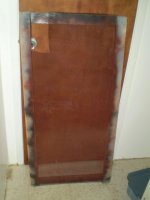
I had started this nearly two years ago and I had stretch the wire mesh on a simple frame and started using up what I had (see Photo).
As best I can remember the base coat was in this order,
Sherwin Williams 988 self etching primer.
Then a gloss black sealer either Plasti-kote or Rust-oleum as it was left over from painting the engine bay of my car.
Then a red sandable primer Rustoleum 2067 or again could have been Plasti-kote red oxide type.
Looking up the data sheets on these showed no type of pigment but they had a high solid content of Talc as well as the etching type.
The grays listed a high content of Titanium Dioxide and thus the reason for choosing the reds instead.
I believe the etching primers may have had a small content of Titanium Dioxide thus the reason for sealing it with the black as I didn't have enough clear at the time.
I would have to re-lookup the data sheets to verify this as I believe one of them doesn't list Titanium Dioxide as an ingredient.
Past experience (reading) has showed the black is better than the white due to the carbon black being encapsulated in the plastics, Although I have not fully tested this theory yet.
Then, I used Rust-Oleum painters touch Ultra cover 2x Gloss clear, 249117 GLOSS CLEAR.
I used a whole can on about half of the panel.
Much got wasted due to the holes, but, the 2X formula gave a very nice build up and this was good to around 2Kv to 3Kv or so on the sample that I had cut out.
But I knew that this was still to thin besides.
Then I sprayed it with some Dutch boy Fresh look Acrylic Enamel (3733 clear) that I had left over from resealing my Powder coated panels before.
And this was the First test that I had posted.
Then I gave it another good coat of it and is where I am now with the latest test.
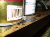
A photo shows where a pinhole had got in the can some years ago and the material had leaked out.
This had been the inspiration as too what exactly this stuff is and if it would work or not.
As it appeared to be the same thing as a solid acrylic sheet material.
Recently I had found some Clear Acrylic spray at the local Pamida thrift store for $1.68 a can (240880 ACRYLIC CLEAR).
It appears to be the same stuff and is what I used on the last panel that had failed.
But as I had already stated this was not the reason for the failure of that panel.
The 2X Rust-Oleum is a very good buy and seems to give at least 3x more material per can, Than a can of the regular stuff for actually a little less than the same price.
And, The $1.68 a can stuff is at least 1/3 the price of a can of the Rust-Oleum brand.
The bottom line is that it is all Clear Acrylic.
From the extensive searching that I have done, they seem to all be the same stuff.
I know that polyurethane is great for high voltages but it is normally an oil based product and it takes a long time for it to fully cure.
Unless, You get the automotive stuff and this can cost as much as 2 to 5 times the cost, not to mention the equipment needed to spray it.
It is not cost effective to buy it in a spray can it is much to thin I have already tried this.

jer
Mostly Rustoleum products.
The etching primer that I used was Sherwin Williams that I had bought 10 cans of, and, on all but two of the spray cans the valve on them failed too work.
As you can imagine I was not happy,But this stuff is some durable and hard paint besides.
I had started this nearly two years ago and I had stretch the wire mesh on a simple frame and started using up what I had (see Photo).
As best I can remember the base coat was in this order,
Sherwin Williams 988 self etching primer.
Then a gloss black sealer either Plasti-kote or Rust-oleum as it was left over from painting the engine bay of my car.
Then a red sandable primer Rustoleum 2067 or again could have been Plasti-kote red oxide type.
Looking up the data sheets on these showed no type of pigment but they had a high solid content of Talc as well as the etching type.
The grays listed a high content of Titanium Dioxide and thus the reason for choosing the reds instead.
I believe the etching primers may have had a small content of Titanium Dioxide thus the reason for sealing it with the black as I didn't have enough clear at the time.
I would have to re-lookup the data sheets to verify this as I believe one of them doesn't list Titanium Dioxide as an ingredient.
Past experience (reading) has showed the black is better than the white due to the carbon black being encapsulated in the plastics, Although I have not fully tested this theory yet.
Then, I used Rust-Oleum painters touch Ultra cover 2x Gloss clear, 249117 GLOSS CLEAR.
I used a whole can on about half of the panel.
Much got wasted due to the holes, but, the 2X formula gave a very nice build up and this was good to around 2Kv to 3Kv or so on the sample that I had cut out.
But I knew that this was still to thin besides.
Then I sprayed it with some Dutch boy Fresh look Acrylic Enamel (3733 clear) that I had left over from resealing my Powder coated panels before.
And this was the First test that I had posted.
Then I gave it another good coat of it and is where I am now with the latest test.
A photo shows where a pinhole had got in the can some years ago and the material had leaked out.
This had been the inspiration as too what exactly this stuff is and if it would work or not.
As it appeared to be the same thing as a solid acrylic sheet material.
Recently I had found some Clear Acrylic spray at the local Pamida thrift store for $1.68 a can (240880 ACRYLIC CLEAR).
It appears to be the same stuff and is what I used on the last panel that had failed.
But as I had already stated this was not the reason for the failure of that panel.
The 2X Rust-Oleum is a very good buy and seems to give at least 3x more material per can, Than a can of the regular stuff for actually a little less than the same price.
And, The $1.68 a can stuff is at least 1/3 the price of a can of the Rust-Oleum brand.
The bottom line is that it is all Clear Acrylic.
From the extensive searching that I have done, they seem to all be the same stuff.
I know that polyurethane is great for high voltages but it is normally an oil based product and it takes a long time for it to fully cure.
Unless, You get the automotive stuff and this can cost as much as 2 to 5 times the cost, not to mention the equipment needed to spray it.
It is not cost effective to buy it in a spray can it is much to thin I have already tried this.
jer
Attachments

Last edited:
I few hours ago I had given my sample one more good coat and I just tested it.
Success !!!!!
Except for one spot of course.
This spot is the one that I had mentioned that some of the primer coating had chipped off.
Most likely it could be fixed by building up the thickness on that one very small nearly microscopic spot.
This is much better than 10 or 20 or more spots that I had to fix on the last panels without getting past 10Kv.
The whole area of the coated sample with held all of the 13.8Kv that I applied with no leakage what so ever!
Except of course that one Dang spot!!!! 
That spot did have a good coating of clear on it but it was missing the Talc primer base.
This may be the key as I will investigate this further when I get a piece coated without a primer base.
Yeah!!!!!

jer
Success !!!!!
Except for one spot of course.
This spot is the one that I had mentioned that some of the primer coating had chipped off.
Most likely it could be fixed by building up the thickness on that one very small nearly microscopic spot.
This is much better than 10 or 20 or more spots that I had to fix on the last panels without getting past 10Kv.
The whole area of the coated sample with held all of the 13.8Kv that I applied with no leakage what so ever!
Except of course that one Dang spot!!!!
That spot did have a good coating of clear on it but it was missing the Talc primer base.
This may be the key as I will investigate this further when I get a piece coated without a primer base.
Yeah!!!!!
jer
Last edited:
I have been doing some more test on the common acrylic enamels that I have been using.
In this test I tried to coat some wire mesh without using a primer this time, and, it did not turn out so good !
Didn't have any more of the 2X stuff and I focused on using the Pamida cheepy brand.
As it turns out the material itself works very well and I suspect a performance of close to 3kv per mil but this is very marginal as I will explain this in greater detail after a few more test setups.
The problem that turned up in this test is the inconsistency's in the coating thickness on such a thin gauge of wire.
This material is much thinner than the 2x stuff and may not have been as much of a problem had I used the 2X material.
But, I don't have any more right now.
It had no problem flowing out at all, infact it flowed too much and caused many thin spots.
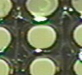
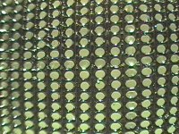
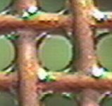
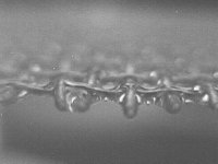
Capillary action caused the first few coats to concentrate in the voids where the wires cross each other forming little beads at each cross point.
This is the very same thing that happened with the very first layer of powder coating as well in which I had too have coat another applied.
But when the second layer of powder coat was applied it was either to thick or not consistent and you could tell the way it flowed out which way it was sitting in the oven.
As I recall the primer did not do this when I first applied it to the wire mesh.
One very good reason to use a primer as most painters will tell you.
Also it also fills the voids were the wires cross each other as well as giving strength in this area for flexing of the wire mesh without causing possible cracking of the coating in these areas.
I may have the primer a bit thick in this first sample but it did work.
I have to get some more in order to try it a gain anyhow for some new stators.
Although I will use what I have already done for now in the next build.
The one thing I did different in this test was to soak the sample wire mesh in an strong etching solution of Lye (sodium hydroxide) to get rid of the top aluminium oxide layer.
This greatly increased the conductivity through the wire mesh.
I had hoped that the roughened surface would help the flowout of the coating but I believe that this had a marginal effect.
Although I am sure that the roughened surface did help it adhere well to the wire anyhow and have not experienced in chipping of the coating as of yet.
I did not do this with the original sample or last builds, although I can still get a continuity reading, it does prove difficult at times.
My last panels did work just fine without this procedure.
One out of the last pair of panels (powder coated ones) showed that there may have been some sort of issue with this.
As they were Identical but one showed a capacitance reading on my meter of 35pf as it should and the other showed 13pf.
Hmmmmmmm...........this made me very sceptical although it worked fine,But it did show some rather odd behavior as I varied the bias voltage.
More on this later when I get a new one running.
I have been flexing the first sample a lot, more so than the average handling for construction, and, I have not had any extra cracking or leakage in tests of the coating so far.
It still with holds 13.8Kv with no problems.
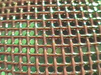
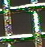
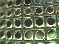
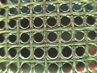
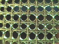
Here are some close up shots of the wire mesh coating buildup vs a cut edge of the original primer'ed sample.
As you can see, It is a big difference in the quality of the coating.
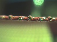
In my next tests I had changed to using 1/16" copper coated TIG rod in order to achieve some more accurate measurements of coating thickness's and volts per mil readings by eliminating the interference of the sharp edges from using the wire mesh.
I will post those results shortly once I compile all of the pictures and data.
The total thickness of this sample is about 30 mil this gives me a coating thickness of about 5 mil to 6 mil but as you can see in the photos the thin spots proved difficult to get a reliable puncture voltage reading as well as some spots where quite thick.
enjoy !!!
jer
In this test I tried to coat some wire mesh without using a primer this time, and, it did not turn out so good !
Didn't have any more of the 2X stuff and I focused on using the Pamida cheepy brand.
As it turns out the material itself works very well and I suspect a performance of close to 3kv per mil but this is very marginal as I will explain this in greater detail after a few more test setups.
The problem that turned up in this test is the inconsistency's in the coating thickness on such a thin gauge of wire.
This material is much thinner than the 2x stuff and may not have been as much of a problem had I used the 2X material.
But, I don't have any more right now.
It had no problem flowing out at all, infact it flowed too much and caused many thin spots.
Capillary action caused the first few coats to concentrate in the voids where the wires cross each other forming little beads at each cross point.
This is the very same thing that happened with the very first layer of powder coating as well in which I had too have coat another applied.
But when the second layer of powder coat was applied it was either to thick or not consistent and you could tell the way it flowed out which way it was sitting in the oven.
As I recall the primer did not do this when I first applied it to the wire mesh.
One very good reason to use a primer as most painters will tell you.
Also it also fills the voids were the wires cross each other as well as giving strength in this area for flexing of the wire mesh without causing possible cracking of the coating in these areas.
I may have the primer a bit thick in this first sample but it did work.
I have to get some more in order to try it a gain anyhow for some new stators.
Although I will use what I have already done for now in the next build.
The one thing I did different in this test was to soak the sample wire mesh in an strong etching solution of Lye (sodium hydroxide) to get rid of the top aluminium oxide layer.
This greatly increased the conductivity through the wire mesh.
I had hoped that the roughened surface would help the flowout of the coating but I believe that this had a marginal effect.
Although I am sure that the roughened surface did help it adhere well to the wire anyhow and have not experienced in chipping of the coating as of yet.
I did not do this with the original sample or last builds, although I can still get a continuity reading, it does prove difficult at times.
My last panels did work just fine without this procedure.
One out of the last pair of panels (powder coated ones) showed that there may have been some sort of issue with this.
As they were Identical but one showed a capacitance reading on my meter of 35pf as it should and the other showed 13pf.
Hmmmmmmm...........this made me very sceptical although it worked fine,But it did show some rather odd behavior as I varied the bias voltage.
More on this later when I get a new one running.
I have been flexing the first sample a lot, more so than the average handling for construction, and, I have not had any extra cracking or leakage in tests of the coating so far.
It still with holds 13.8Kv with no problems.
Here are some close up shots of the wire mesh coating buildup vs a cut edge of the original primer'ed sample.
As you can see, It is a big difference in the quality of the coating.
In my next tests I had changed to using 1/16" copper coated TIG rod in order to achieve some more accurate measurements of coating thickness's and volts per mil readings by eliminating the interference of the sharp edges from using the wire mesh.
I will post those results shortly once I compile all of the pictures and data.
The total thickness of this sample is about 30 mil this gives me a coating thickness of about 5 mil to 6 mil but as you can see in the photos the thin spots proved difficult to get a reliable puncture voltage reading as well as some spots where quite thick.
enjoy !!!
jer
Attachments
-
 CP1.jpg235.3 KB · Views: 106
 -
 CLEAR 5 ENDb.jpg31.5 KB · Views: 90
 -
 CLEAR 5 ENDa.jpg43.2 KB · Views: 80
 -
 CLEAR 4 ENDd.jpg51.3 KB · Views: 84
 -
 CLEAR 5.jpg281.2 KB · Views: 85
 -
 CLEAR 4.jpg284 KB · Views: 90
 -
 CLEAR 3.jpg324.5 KB · Views: 99
 -
 CLEAR 2.jpg339.4 KB · Views: 103
 -
 CLEAR 1.jpg294.1 KB · Views: 134
 -
 CP7.jpg204.6 KB · Views: 96
I just ordered AC-43 polyester conformal coating in spray bottles, it was the best I could find in Finland.
Some info:
Dielectric strength at 23 ° C and 50% r.F. kV / mm ≥ 80 kV / mm (2kV per mil)
Surface resistance at 23 ° C ≥ 10^15 Ω Ω * cm * cm
Surface resistance after 96 h storage in water ≥ 10^12 Ω * cm * cm Ω
Dielectric constant at 23 ° C between 50 Hz and 1 MHz (1.5 ± 0.5)
Dissipation factor at 23 ° C between 50 Hz and 1 MHz ≤ 15.10^-3
Loss factor of 0.2 = Point of intersection 200.10-3 ≥ 78 ° C
It should dry hard but flexible coating, and it's compatible with all other coatings there might be underneath like epoxy based powder coating. I hope it also dampens the stators a little. Capacitive effect is very small due to low dielectric constant value.
Has anybody tried polyester based conformal coatings on esl stators?
I changed from above mentioned polyester based "real" insulation coating to (solvent thinned) high gloss urethane-alkyd varnish that has 48% solids. Polyester gets too expensive if I ever wanna do a thick coating. I have rolled on couple of layers and it smoothens out guite nicely, looks very glossy (like it's wet when it's not), and applying is way faster than spraying, which I did before. The stuff does not get like epoxy-hard, but stays a bit elastic even though is very hard and durable. Good for curved stators. Hopefully it insulates at least 400V per mil. I will do many many layers.
Regards,
Legis
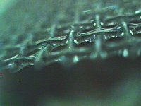
edit. here's a close-up after 2 coats of high gloss black powder coat, 5 coats of conformal coating and 5 coats of rolled urethane-alkyd varnigh on top (stator is 18 ga). Does not look like much.
.Regards,
Legis
edit. here's a close-up after 2 coats of high gloss black powder coat, 5 coats of conformal coating and 5 coats of rolled urethane-alkyd varnigh on top (stator is 18 ga). Does not look like much.
An externally hosted image should be here but it was not working when we last tested it.
Last edited:
Hello Legis,
I too have found that the greatest concentration of alkyds solids was available in a furniture spar urethane (Helmsman). I would venture to guess by the appearance of your stators your probably done. How much voltage will you be using, will you be performing an arc test to verify coatings?
Did you roll this on?
I wonder if dipping the stators into urethane may be a viable coating option? I will be exploring this possibility.
Hello Legis,
I too have found that the greatest concentration of alkyds solids was available in a furniture spar urethane (Helmsman). I would venture to guess by the appearance of your stators your probably done. How much voltage will you be using, will you be performing an arc test to verify coatings?
Did you roll this on?
I wonder if dipping the stators into urethane may be a viable coating option? I will be exploring this possibility.
Hi, I'm using this stuff: Products in alphabetic order - Tikkurila | Decorative Paints | Products
I plan to use 6-8kV bias on 3mm d/s. Drive voltages max. 5300Vpeak (50Vrms to 1:75 step up). I wish I had a HV wand to test the coating but I quess I just have to apply thick coating and wish for the best.
Yep rolling works very well for me. A foam roller gives the smoothest result. I don't thin the stuff before applying. The roller naturally instroduces visible air bubles into the coating but they can be rolled out by rolling very gently over them couple of times and the bubles disappear. I cannot detect any bubbes with a bare eye from dryed coating.
Legis,
here is a better link to what I used Exterior Clear Protective Finishes | Wood Products it essentially looks like a similar product.
For the H.V. wand you can use your power supply and connect one end to your stator and the other to an insulated handle screwdriver connected by alligator clips, then use tinfoil to drape across the screwdriver to essentially drape across the insulation. I typically do this on the granite counter top with low lighting and the wife nowhere insight, also do this in a quiet room to possibly hear any sizzling.
Hi, I tried the spark test with the bias supply after 24h cure time. The stator was connected to the step up trafo, and the aluminum coated mylar was biased, aluminum side turned against the stator. At 2,2kV nothing sparked through although the membrane got sucked pretty hard into the stator and the neon bulb blinked like hell. I boosted the bias to current maximum 4,7kV, the neon bulb was lit all the time and I got two sparks near the center area after 10-15 seconds. They left spots on the mylar so I know where they got through.
I quess I just insulate those spots, put on 2 extra layers on the whole panel on both sides, and the panel is quite ready after that... I will also test the front stator with the same method after I have put more layers on it's front side first.
I quess the insulation works quite well.
I quess I just insulate those spots, put on 2 extra layers on the whole panel on both sides, and the panel is quite ready after that... I will also test the front stator with the same method after I have put more layers on it's front side first.
I quess the insulation works quite well.
An externally hosted image should be here but it was not working when we last tested it.
- Status
- This old topic is closed. If you want to reopen this topic, contact a moderator using the "Report Post" button.
- Home
- Loudspeakers
- Planars & Exotics
- High strength Dielectric Coatings, fact or fiction