A flat voltage response fed to a dipole ESL will result in a rising acoustice response.
So, you need to flatten the acoustic response by some means...electrically with series resistance and/or shelving type filters in the primary or secondary circuits, or acoutstically with segmentation.
AHA!!!!!*
Can you provide some sense of what that rising relationship is? 6dB/8ave? (That's not the same as saying all or any of us think the treble needs cutting after listening in our music rooms or that "flat" is sacrosanct.)
Thanks.
Ben
*OK... I can't remember much from reading from reading Hunt a long time ago.
Last edited:
I'm planning to use this module for the HV bias supply:
CS2080A3: HIGH VOLTAGE POWER SOLUTIONS: Power Supplies & Wall Adapters
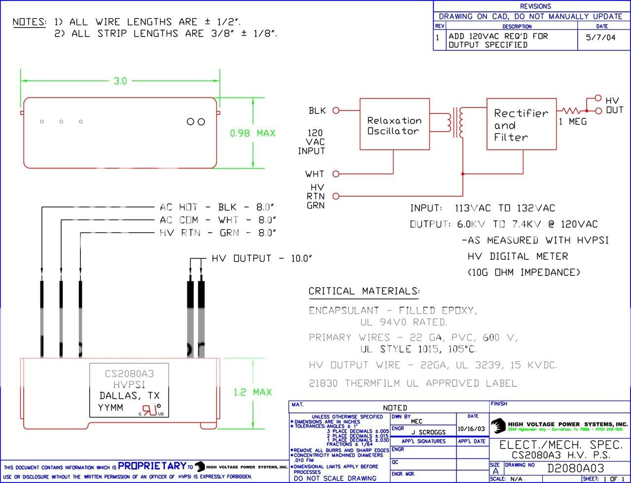
Does anyone see any problems with this?
Also, why do I always see the bias supply with the negative hooked up to the mylar? I would think either positive or negative would work.
CS2080A3: HIGH VOLTAGE POWER SOLUTIONS: Power Supplies & Wall Adapters
Does anyone see any problems with this?
Also, why do I always see the bias supply with the negative hooked up to the mylar? I would think either positive or negative would work.
Last edited:
I'm planning to use that supply only on my bass panels which will have .125" spacers, so I don't think that will be a problem. But I understand your concern. I've got all the parts to build a ladder type supply, but this item is so simple and compact I'd like to use it if possible.
That looks like a nice little unit however I am sure that it is quite costly.
A variable supply can be made very cheaply and should any thing happen like a diode shorting out can be easily replaced rather than replacing the whole unit.
I have lost a few diodes in the past and had to replace them but not lately.
I have a simpler design in mind that is less complicated than the one I just did and would still be variable.
As well as by adding more stages you can get to any peak voltage range you desire or need .
It makes no difference rather you use positive or negative on the diagphram there have been some discussion as to whether or not it helps to keep the dust from collecting on it by using the negative side.
But as far as the sound goes reversing the polarity of the bias will just reverse the polarity of the sound wave coming from the driver is all.
jer")
A variable supply can be made very cheaply and should any thing happen like a diode shorting out can be easily replaced rather than replacing the whole unit.
I have lost a few diodes in the past and had to replace them but not lately.
I have a simpler design in mind that is less complicated than the one I just did and would still be variable.
As well as by adding more stages you can get to any peak voltage range you desire or need .
It makes no difference rather you use positive or negative on the diagphram there have been some discussion as to whether or not it helps to keep the dust from collecting on it by using the negative side.
But as far as the sound goes reversing the polarity of the bias will just reverse the polarity of the sound wave coming from the driver is all.
jer
That looks like a nice little unit however I am sure that it is quite costly. jer
They are actually quite cheap at $11.00 each. At that price I could buy a few spares.
Can you provide some sense of what that rising relationship is? 6dB/8ave? (That's not the same as saying all or any of us think the treble needs cutting after listening in our music rooms or that "flat" is sacrosanct.)
The far-field native response of all unbaffled dipole ESLs is a rising response with increasing frequency.
(+6dB/octave for point source like QUAD ESL63, +3dB/octave for line source like Acoustat 1+1)
The +6dB/octave slope of the point soure dipole ESL is easily "flattened" by resistance inserted between the step-up transformer output and ESL stators. The larger the resistance, the larger bandwidth over which the response will be flat. Larger resistors emulate constant current drive. The Walker equation shows that if the current fed to a point source dipole ESL is constant, the far field response will be flat.
More info on current drive in this thread: (including link to ESL simulator)
http://www.diyaudio.com/forums/planars-exotics/175918-current-vs-voltage-drive-esl.html#post2343151
http://www.diyaudio.com/forums/plan...rrent-vs-voltage-drive-esl-6.html#post2353285
The +3dB/octave slope of the line source dipole ESL is a bit more troublesome to equalize flat. One approach is to use segmentation, increasing the driven area with falling frequency at the rate required to offset the 3dB/octave slope. Acoustat used a 2 transformer electrical shelving circuit to get a flat response with the 1+1s.
More info on line soures and segmentation in this thread:
http://www.diyaudio.com/forums/planars-exotics/48120-experiences-esl-directivity-6.html#post2202327
Later in the thread I posted some spreadsheets to help with segmentation calculations:
http://www.diyaudio.com/forums/planars-exotics/48120-experiences-esl-directivity-7.html#post2204784
http://www.diyaudio.com/forums/planars-exotics/48120-experiences-esl-directivity-9.html#post2218526
They are actually quite cheap at $11.00 each. At that price I could buy a few spares.
Not bad,That is a very good deal!
I had expected them to be much more than that.
That is the cheapest I have seen for a ready made supply so far.
Lets us know how well they work when you get to that point.
jer
Last edited:
One thing that comes to mind is that on the data sheet the voltage range is specified as 6.4kv to 7kv.
A 600v difference,what guarantees the consistency between two units for one per panel?
Believe it or not a 500v change in bias is quite noticeable.
Although most DIY supply's are not regulated I would think that they would very consistent as per unit provided they were made from exactly the same parts.
I may be overly concerned about this,But it is something to think about.
As it is not about what voltage they output,But about the difference between two units and how much this is difference is affected should the input line voltage change and fluctuate.
jer
Last edited:
But, I think only one unit is needed. And that spec may reflect the spec for input voltage 120-138v or something. But I think it is safe to think a $10 device of this sort of circuit might have an output voltage plus-or-minus 20%.
Another problem is that the voltage seems rather high, at least to my intuition. Also, seems incautious (nice word, eh) to have engineering faith (nice term, eh, much nicer than "blind faith") that it is the "correct" bias voltage instead of simply having some means of trimming the voltage as needed after construction.
Ben
One thing that comes to mind is that on the data sheet the voltage range is specified as 6.4kv to 7kv.
A 600v difference,what guarantees the consistency between two units for one per panel?
jer
They are rated as 113V to 132V input for an output of 6KV to 7.4KV. Where I live the voltage runs pretty steady at 120V so I would guess these modules will provide about 6.4KV output. I think this will work with a.125" spacing. When I first power up the panels I'll use a variac and see how it goes. At the first sign of sizzle, I'll back off.
Last edited:
If you do stress check on the panels with that supply after they are coated and get no arcs I don't foresee any issues with such a large D/S.
I used to run My little panels up into that range with a D/S of about .075".
But the coating is also thick enough to with stand those kinds of voltages.
Normaly in free air using sharp points it would jump a 6mm gap.
In a few days I will have my panels back running (again after a year) now that I have the power supply almost finished.
I will be back to square one with one of them.
One of the screen stators got ripped from something ( a speaker box fell on it from way up high ).
I will have to repair it and reseal it in order to get it back to that level of voltage again.
I am patient ,But I can't wait because this will be the first time that I will be listening to them in stereo again since 2003 when I first made them.
All of the tests I made last year were done in mono, Because a was observing the nuances of each individual panel and configurations that I was trying out.
Running them in stereo would have distracted me from the things that I was trying to find.
Even in mono they were incredible no mater what configuration and how many panels I used.
jer
I used to run My little panels up into that range with a D/S of about .075".
But the coating is also thick enough to with stand those kinds of voltages.
Normaly in free air using sharp points it would jump a 6mm gap.
In a few days I will have my panels back running (again after a year) now that I have the power supply almost finished.
I will be back to square one with one of them.
One of the screen stators got ripped from something ( a speaker box fell on it from way up high
).I will have to repair it and reseal it in order to get it back to that level of voltage again.
I am patient ,But I can't wait because this will be the first time that I will be listening to them in stereo again since 2003 when I first made them.
All of the tests I made last year were done in mono, Because a was observing the nuances of each individual panel and configurations that I was trying out.
Running them in stereo would have distracted me from the things that I was trying to find.
Even in mono they were incredible no mater what configuration and how many panels I used.
jer
I wonder if anyone on the forum has used one of these amps:
BEHRINGER: NU3000DSP
It's a new amp from Behringer that has a built in DSP with x-over and a lot of other features. I'm thinking of using a pair to drive my speakers when they are done. The xlr inputs don't bother me since that is what I'm using anyways with my Denon AVP-A1HDCI preamp.
BEHRINGER: NU3000DSP
It's a new amp from Behringer that has a built in DSP with x-over and a lot of other features. I'm thinking of using a pair to drive my speakers when they are done. The xlr inputs don't bother me since that is what I'm using anyways with my Denon AVP-A1HDCI preamp.
I have a bunch of 125 Mohm 5 watt metal film resistors that I bought many years ago. I would like to use these for the HV bias resistors. Would these work, or are they too high?
125Mohm will work just fine.

In practice, anything between 10Mohm - 500Mohm will do.
I have used common 1/4 watt 10megohm resistors from radio shack to feed my panels from the bias supply with no problem.
The only time I lost one was from arcing to a ground wire when I was testing the supply and the ground wire was to close to the resistor body and the arc punctured the protective casing and burned it,that was the only failure so far.
jer
The only time I lost one was from arcing to a ground wire when I was testing the supply and the ground wire was to close to the resistor body and the arc punctured the protective casing and burned it,that was the only failure so far.
jer
My design is going to be two woofer panels per side with radiating areas of 60" by 8.5" using .5 mil mylar and .125 DS spacing. The mid, highs will come from one panel per side with a radiating area of 60" by 3.5" using .25 mil mylar and .0625 DS spacing. Bias for the woofers will be in the order of 5000 to 7000 volts. The mid/tweeter will be biased at 2500 to 3500 volts. Woofers will use two Oil burner transformers per side and mid/tweeters will use two to four toroids per side.
If I can get the oil burner transformers to work up to about 400 Hz, do you think the radiating area of the mid/tweeter will produce enough output to cover the rest of the spectrum?
If I can get the oil burner transformers to work up to about 400 Hz, do you think the radiating area of the mid/tweeter will produce enough output to cover the rest of the spectrum?
Yes,that sounds like a good combination.
That is pretty much what I had in mind of doing at one time.
I ran my 3.25' wide panel at about 5.5Kv to 6.5Kv with with a very high transformation ratio (200 to 400 :1) and a big amp (crown DC300a) it is was louder than any woofer system I had at the time.
And,Louder than I could stand in this room and that was for one panel.
I will be getting it running very soon and I can't wait to put it up against the woofer system I now have.
And then I will start on the longer versions of the same panel.
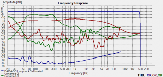
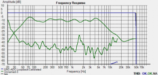
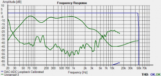
Here are some in room response charts.
jer
That is pretty much what I had in mind of doing at one time.
I ran my 3.25' wide panel at about 5.5Kv to 6.5Kv with with a very high transformation ratio (200 to 400 :1) and a big amp (crown DC300a) it is was louder than any woofer system I had at the time.
And,Louder than I could stand in this room and that was for one panel.
I will be getting it running very soon and I can't wait to put it up against the woofer system I now have.
And then I will start on the longer versions of the same panel.
Here are some in room response charts.
jer
Attachments
Last edited:
- Status
- This old topic is closed. If you want to reopen this topic, contact a moderator using the "Report Post" button.
- Home
- Loudspeakers
- Planars & Exotics
- Some More Questions On ELS Design