Hi All
I wonder if anybody may be able to answer a few questions behind the design of some of the apogee ribbons .
I have been review their patent no.4550228 and find the following puzzling:
a) The midrange ribbon is noted as being attached at the edges along its length to the frame /diffraction thingos etc. as opposed to being limply suspended in space.
Whilst this would help with mechanical centering of the ribbon, I would have though that any such fixing would have restricted any ribbon movement and even lead to very high local stresses in the membrane leading to failure at the point of attachment .
I also note that the ribbon appears to be obliquely corrugated as opposed to perpendicular to its length - ie as the treble ribbon is. =perhaps this allows for some movement without mechanical failure.
From memory some of the magnepan treble ribbons were also attached at the edges ..??)
b) The treble ribbon seems freely suspended but has what appears to be a significant gap at the edges near the face of the magnets to each side .
I would have thought this to be a no-no for sound cancellation - or is this gap not an issue at the frequencies in question? (This gap is also plainly visible in some of the images of the ribbon found on the net.)
c) There also appears to be gaps between the magnets in their vertical positions - I would have thought to have them touching was desirable - or maybe the gaps are a concession to the difficulty in positioning the magnets at time of manufacture??
Any comments ?
Cheers
Hi George,
This Apogee patent is for their Full Range Ribbon Speaker.
The midrange ribbon is a true ribbon made from 10 micron thick aluminum foil with horizontal corrugations over the 2" wide, 84" long ribbon. The ribbon is clamped at the top and bottom by copper bars. To control resonance, the ribbon is physically divided into three equal lengths by soft foam rubber pads that contact both the front and rear of the ribbon to physically center-clamp the ribbon in the frame. Hence, the ribbon is one aluminum strip, but it is physically divided by the foam rubber clamps into three separate physical segments. The ribbon is 0.1 ohms, and almost pure resistance. A metal box holds a step up transformer that converts the 0.1ohm to 4ohm. The speaker comes with a passive front end bi-amp crossover box which provides 1st order crossover slopes at 320Hz and 10K Hz.
The magnet structure for the midrange is designed to provide a self-centering force. Two rows of ceramic magnets with about 0.1" separation are glued along the length of the iron frame. This 2-magnet-gap motor structure provides a more uniform magnetic field over the front-rear ribbon displacement. A second method is used to help self-center the ribbon. At the top electrical connection, two aluminum foil strips are run along the magets on both the left and right sides down to the floor, where the input started. Plastic tape on top of the magnets electrically isolates the foil, and a second strip of plastic tape on top of the foil provides electrical isolation from the ribbon. Remember that this ribbon is only 84 db/watt efficiency, so large currents flow through these side aluminum foils. A more efficient NdFeB ribbon would not generate enough current to make this side-foils arrangement worth considering.
The tweeter ribbon is constructed from a 0.5" wide, 2*84" long 10 micron aluminum foil with horizontal corregations. The two ends are both electrically connected at the bottom of the ribbon, and the top is a non-conductive clamp. The 2x length is used to create a bipole tweeter with about 0.5" air gap between the front and rear tweeter foil. When the drive current pushes the front ribbon forward, the rear side is pushed backward, thus creating a bipole radiation. Using one long strip of foil increases the total resistance to 2 ohms, and increases the efficiency to where Apogee used just a 2 ohm series resistor instead of a step-up transformer. The tweeter ribbon also uses two sets of soft foam rubber pads to physically divide the ribbon into three equal pieces, over just one continuous foil.
For comparison, the Magnepan true ribbon tweeter ribbon uses extremely thin 2 micron thick aluminum foil to create a 4 ohm resistive load that is easy and cheap to direct drive by an amp. The ribbon is horizontally corrugated, and a small blob of silicone between the ribbon edge and iron frame in several places along the length is used to physically divide the single foil strip. This protects the delicate foil from stretching from a puff of air and SPL abuse.
Last edited:
Yes Linesource - a most informative and concise post!
Many thanks for going to the trouble to respond.
I can't help but wonder if the foam block restraints on the apogee ribbons or the silicone blob securing on the magnepan doesn't lead to some "work hardening" of the metal foil and premature failure at the points of attachment/ restraint.
Or maybe the forces involved just aren't strong enough to be an issue ..
any comments
thanks
The foam rubber "clamps" on the Apogee Full Range ribbons can be adjusted to better serve as "displacement stops" where the ribbon can move forward/backward about +/- 0.1" before touching the soft foam rubber. This is how I set up my speakers. Hence the "clamp" pad position protects the ribbons during transport, and "displacement stop" pad position protects the ribbon from having bass notes push the ribbon out of the channel to where the corrugations stretch. It is easy to see the Apogee midrange ribbon move during bass notes from the shallow 6db/oct 320Hz crossover. You cannot see tweeter ribbon movement. Hence, the 10 micron aluminum foil used by Apogee is strong enough to "stand alone" over the 84" length under reasonable SPL levels. To my ears, 10 micron aluminum is also thick enough to "sizzle" from resonances.
The 2 - 2.5 micron thick Magnepan ribbon can be broken by a strong puff of breath, and hence the silicon globs that attach the ribbon side edge to the metal frame are mandatory to maintain reliability, as well as maintain ribbon/frame centering. Magnepan forums mention a high ribbon failure rate due to the super thin foil. From what I have read I believe that the glue joint does work harden the ribbon foil, but it is mainly using usper thin foil that causes the frequent failures. Magnepan may use a 5056 Al alloy for greater strenth.
My DIY ribbons use 5.6 micron thick pure Al foil. This is thick enough for adequate physical strength, yet "soft" enough not to sizzle. Wiggle cheap household Al foil (12.5 - 25 micron thick) and it makes a lot of noise. Thinner foils seem to self-dampen these vibrations and are quiet.
There are many reasons why metal foil + plastic film are married by some magic to make strong, quiet ribbons.
Last edited:
Hi Linesource and others
There is some talk about application of vaseline to some part of the ribbon foil of Decca / Kelly ribbons to control resonances (I think) but this may be an obscure art..?
May I ask what gap there may typically be between the edge of a ribbon and the magnets adjacent
In photos i have seen of the Apogee ribbons - it appears that this gap can be quite large...
Additionalyl in some photos there is a substantial length of ribbon at each end which does not have magnets either side - I wonder if this is a problem area subto resonaces as it is possibly not subject to any or much EMF...
Any comments anybody?
Thanks
in some photos there is a substantial length of ribbon at each end which does not have magnets either side - I wonder if this is a problem area subto resonaces
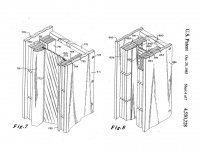
Many ribbon designers attempt to absorb the resonant ribbon energy at the top and bottom attachment points. RAAL uses a cantelever mount with heat shrink plastic film tensioning. This construction provides a suspension without increasing height that can effect directivity control. Some long Al ribbon patents show significantly larger corrugations at the top and bottom ribbons portions where no magnetic field exists. Some long ribbons use soft foam rubber at the clamp points, both to reduce foil rip from vibration, and to absorb ribbon energy before it gets reflected back.
Some suspension is required for the ribbon. It is best to keep this non-linear-motion-suspension portion out of the magnetic field so it can effectively dampen out the ribbon's energy.
Attachments

Hi all
Many many thanks to you all for the considerable effort you've out into responding to my queries.
I will will be attempting to (re)build some 24" ribbons over Christmas . (wider ribbons this time)
This will be the second attempt as the first ones self-desructed when I carried one completed assembly across the room - too close to another assembly leaning against the wall.
Luckily fingers weren't caught - but oh what a mess!.....64 of 2" x1/2" sq neos
luckily only a couple broke....
had to completely dismantle the whole thing - magnet by magnet .
No way we could pull these things apart.....
Cheers and thanks again
george a: That magnet condensation event sounds like one for the record books. I think I would have run out of expletives under those conditions. Glad to hear no important body parts were sacrificed.
Linesource: Can you say a bit more about the photos in your last post? How are the parts you showed going to be used?
Few
Linesource: Can you say a bit more about the photos in your last post? How are the parts you showed going to be used?
Few
Linesource: Can you say a bit more about the photos in your last post? How are the parts you showed going to be used?
Few
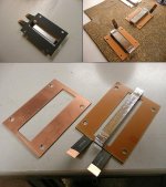
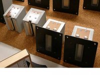
Hi Few,
The first picture is of the RAAL "FlatFoil" ribbon and its mounting frame. This assembly is screwed to the RAAL magnetic+steel frame in the lower left of the second picture to construct the finished ribbon in the lower right of the second picture. RAAL embosses their Al foil and adds a stretchable plastic film for the suspension instead of corrugating the Al foil it as done in most ribbons.
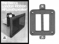
The 1956 Decca London Ribbon was one of the first designs to use a ribbon in a frame for ease of repair.
Attachments
Linesource, does the Apogee double magnets (front and back) really make a difference on field strength.
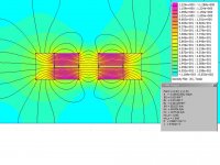
The magnet-gap-magnet motor structure does provide a more uniform field over a longer front-back displacement than a single 2x height stack of the same number of magnets. This motor structure also provides some self centering between large displacement transients. Simulation show that this is a good design option with low flux ceramic magnets, or small NdFeB magnets. (pic1 and sim_pic2)
With larger high strength NdFeB magnets a steel "magnetic lens" (pic3) can be used to maintain a uniform flux over longer front-back displacements.
With even larger, wider, high strength NdFeB magnets the center gap field is uniform enough over a 0.1"-0.2" to not require additional more complicated engineering. I favor this simple construction.
Attachments
Last edited:
The magnet-gap-magnet motor structure does provide a more uniform field over a longer front-back displacement than a single 2x height stack of the same number of magnets. This motor structure also provides some self centering between large displacement transients. Simulation show that this is a good design option with low flux ceramic magnets, or small NdFeB magnets. (pic1 and sim_pic2)
With larger high strength NdFeB magnets a steel "magnetic lens" (pic3) can be used to maintain a uniform flux over longer front-back displacements.
With even larger, wider, high strength NdFeB magnets the center gap field is uniform enough over a 0.1"-0.2" to not require additional more complicated engineering. I favor this simple construction.
Hello,
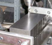
I have the same results with a variation of 3,8%. I bought customized Neodym Magnets 15x15x140mm with such lens milled. But it is very expensive!! Your version of a steel lens is more cheaper. Do you have any idea to manufacture such steel lens?
Andre
Do you have any idea to manufacture such steel lens? Andre
Andre,
Iron and soft steel like alloy 1008 are relatively easy to machine. Any machine shop could easily mill your artwork into a rectangle bar. Some DIY'ers use a drill press with a XY screw vise plus a few milling bits to make these simple shapes.
I do not think a magnetic lens is necessary for a tweeter ribbon, but might be helpful for a midrange ribbon if a smaller, lower cost NdFeB magnet is used. The increase in NdFeB prices has changed what is a cost effective design.
Attachments
Building a full range planar gets rid of all these problems of ribbon delicacy, placement etc. etc. I have just bought a pair of Magnepan SMGbs and I have one of these with latest rebuild and they make a well matched pair! I have rebuilt quite a few improved designs and am still leaning.Will probably rebuild all my rebuilds until I reach the pinnacle of my design, if I live long enough?
- Status
- This old topic is closed. If you want to reopen this topic, contact a moderator using the "Report Post" button.
- Home
- Loudspeakers
- Planars & Exotics
- Apogee ribbon questions...