I'm guessing here as I've never had a broken pair to examine but there are a few ways that could possibly work.
1. punched from the other side
2. some sort of hot glue or other dry set material formed onto the stator with a mould prior to painting
3. solder? - although I don't know how they would get the size right.
1. punched from the other side
2. some sort of hot glue or other dry set material formed onto the stator with a mould prior to painting
3. solder? - although I don't know how they would get the size right.
Hi Oublie,
I think they are epoxy or some kinds of plastic material, because you don't want to create any sharp edges on the stators. These spikes are actually quite stiff and they stuck to the stators quite well.
I always thought that by having spacers in the middle of the stators would somehow affect low frequencies. But even with these many spacers, the low frequencies are still very good in these drivers. Perhaps these spacers do not actually touch the diaphragm. They might just put them there to protect the diaphragm from ever touching the stators. What do you think?
Hi,Wachara,
What would the D/S be?
They could be too not let the diagphram stick to the stator as was suggested and can happen very easily with a very light tension.
When I pushed my little panels to the onset of stator clipping it was barely noticeable until I got passed about 5% clipping distortion.
I was not even aware that this was happening until I saw the signal on a scope from a microphone.
The little bit of distortion that I was hearing I wrote off as the amp clipping,But it was not the amp at all.
It was quite livable at that volume but I did not dare too get my ear that close like a headphone driver would be with that test.
At lower levels my little panels are wonderful for headphone drivers but they are 3 times the length that is needed.
The D/S on those is around 1.5 mm.
There were a few times in various tests that got the diagphrams to stick to the stators (mainly with low tensions),and, Just a little knudge with a toothpick through a stator hole was enough to get it to snap back even though the were still energized.
jer")
What would the D/S be?
They could be too not let the diagphram stick to the stator as was suggested and can happen very easily with a very light tension.
When I pushed my little panels to the onset of stator clipping it was barely noticeable until I got passed about 5% clipping distortion.
I was not even aware that this was happening until I saw the signal on a scope from a microphone.
The little bit of distortion that I was hearing I wrote off as the amp clipping,But it was not the amp at all.
It was quite livable at that volume but I did not dare too get my ear that close like a headphone driver would be with that test.
At lower levels my little panels are wonderful for headphone drivers but they are 3 times the length that is needed.
The D/S on those is around 1.5 mm.
There were a few times in various tests that got the diagphrams to stick to the stators (mainly with low tensions),and, Just a little knudge with a toothpick through a stator hole was enough to get it to snap back even though the were still energized.
jer
can u *.jpg full range?Hi Jer,
The D/S is only 0.35 mm and the stator width is 50 mm. The bias voltage is 580v.
It really is a wonderful, little driver. The bass goes down very deep and the treble is lovely.
Wachara C.
Could the whole surface have been photo etched leaving the spikes?
Why not injection or compression molded? Seems the easiest way.
Hi,
its the trasducers proximity to the ear channel that boosts the bass up to sufficient levels. Measured free-air the amplitude response probably shows a falling response below ~100Hz. So even for low bass-frequencies the excursion may remain small, especially with a such a large transducer as the Stax.
The array of small dots allows for a distribution of resonances and lower Qs of these and secures a proper d/s. The diaphragm movement on a macroscopic level is closer to translatory than bowed. This should also allow for higher possible SPLs.
Manufacturing -even if we don´t know the howto yet- was probabely much easier and cheaper than glueing multiple spacer dots and results in smaller dots, hence less ´dead´ capacitance/diaphragm area.
jauu
Calvin
I'll try putting some silicone dots on the diaphragm and see if it will make any difference in sound. I agree with Calvin that this is a lot easier to do than making the micro spikes.
On the other hands, I do not think that these spikes actually touch the diaphragm. I agree with Oshifis that they are there only to prevent the diaphragm sticking to the stator. I've actually tried to tension my diaphragm using mechanical tension and hand stretch tension techniques. Mechanical tension tends to be too much for these headphones as the bass isn't as good. When I do hand stretch tension, it's a lot better. So, with low diaphragm tension and spacer to diaphragm width ratio of 1:143, my guess is that these spikes help the diaphragm sticking to the stators.
Wachara C.
If the spikes won't touch the Mylar than I think you would hear a rattling sound at higher levels when the Mylar starts to touch the spikes. So these spikes must always touch the Mylar ( and otherwise they could be simply omitted).
While silicon dots offer some great insulation I wonder what these spikes can offer at this point. Of course the voltage requirements are much lower
I own some stax myself for several years and these things work great
While silicon dots offer some great insulation I wonder what these spikes can offer at this point. Of course the voltage requirements are much lower
I own some stax myself for several years and these things work great
Very clever things they are..
Usually when diaphragm hits the stators, there is still lot of unused displacement - often about half of what is achieved when all the diaphragm hits the stators.
Standard support points which touch the diaphragm increase resonance frequency at same tension level, but they do allow to reduce tension and still not touch the stators.
These supports both do not increase resonance frequency and allow reduced tension. When the diaphragm deflects too much it first hits the supports, which seem to be round so this does not produce sound, and is mechanically divided into regions. So in the conditions where with an conventional stator a diaphragm would hit the stators at center of the driver, while it would barely move at edges, with such a dotted stator there would be the whole diaphragm would be deflected almost equally while not touching stators anywhere.
That's how I see it. Would be a PITA to diy though, sadly.
Hello,I wish I have a tool to measure the height of these spikes.
Wachara C.
You can often make measuring devices from stuff around the house. For example, you can make shims from pieces of paper stacking then up until they are the same height. For instance, you could measure the height of a ream of paper and then divide by 500 to find the height of a single sheet. Also you could use the geometry of triangles to "amplify" the height to an easily measurable level.
Umm, but don't you have a CNC machine? Couldn't you make a set of gauges like a small inverted U?
As to the purpose of the spikes, I don't know. But independent of what their purpose is, they will introduce non-linear behaviour to the membrane resulting in something akin to soft limiting - so distortion as high deflection. It would be different if they always touched the diaphragm.
I do not know about them stopping the membrane from sticking to the diaphragm due to electrically generated negative compliance. All I have read has put the mechanical compliance of the membrane due to tension quite high. Whether it is as high as the 3.5 ratio used by Quad, I do not know. Has anyone on the forum experienced a membrane sticking to a stator in Stax phones under normal circumstances - at any level? It would be noticable because the sound would cut out. Of course, this argument could be shot down if you find this particular model is aberrant. Will it be a future design feature or a dead end?
Also, from the photo you supplied, the stator design should preclude the diaphragm being influenced by the thin film behaviour of the air trapped between the membrane and the stator so that one is out.
I can't see how they would affect the behaviour of the primary membrane resonance (apart from the non-linear bit) as this is purely a function of mass, compliance, and damping none of which is altered, at least at reasonable deflections. As to the higher order modes in the membrane, even if the spikes could affect them, I hope the modal deflections are not large enough to contact the spikes - that would be really bad.
Nope, short of tracking down the designer and making him talk, I don't think you will ever know for certain. Another Stax mystery!
Regards,
Bob
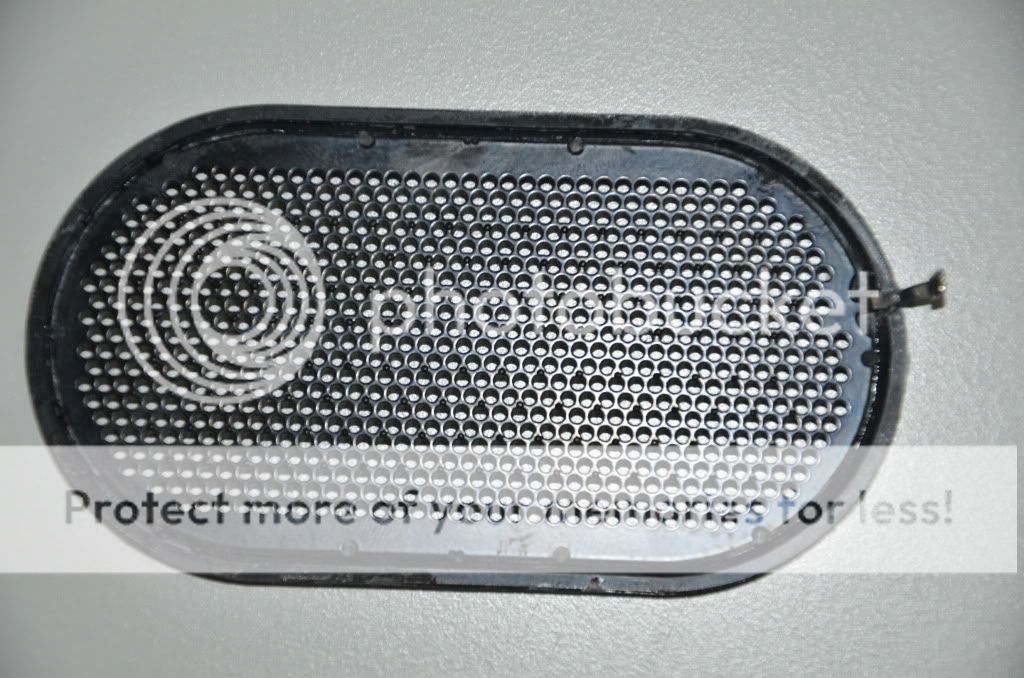
Regards Wachara! Very interesting spikes. No spikes between the outer three holes/rows, and in the middle row they are three holes apart, else just two. Maybe the spikes do a little disloading of the diaphragm when touched. Could you measure the resistance between spikes and stator with a multimeter (probably in the megaohm range) ?
Hi 210,
The Stators are coated with powder coating, I think. I don't have a high voltage resistance meter on hand. So, sorry about that.
I've been thinking about these spikes. Will they be beneficial if we were to put them on full range electrostatic speaker stators?
Wachara C.
The Stators are coated with powder coating, I think. I don't have a high voltage resistance meter on hand. So, sorry about that.
I've been thinking about these spikes. Will they be beneficial if we were to put them on full range electrostatic speaker stators?
Wachara C.
- Status
- This old topic is closed. If you want to reopen this topic, contact a moderator using the "Report Post" button.
- Home
- Loudspeakers
- Planars & Exotics
- Some interesting findings about Stax electrostatic stators