apogee link
Hi
Check this link
Apogee Speaker Users Website
go to repairs section and request a video on how to dismount the tweeter and bass ribbon.
Thanks
Hi
Check this link
Apogee Speaker Users Website
go to repairs section and request a video on how to dismount the tweeter and bass ribbon.
Thanks
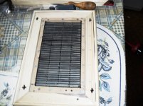
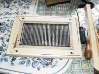
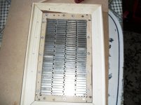
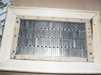
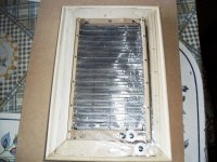
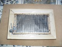
All the pics of the diaphragm are not very revealing on the actual layout of the aluminium vis a vis the magnets. It is easier to see this relationship on the epsilon which gave me the inspiration to change it for various magnet layouts on my latest designs. Which are much more sensitive than my older ones. I will be rebuilding all my older designs about 30 altogether. Have to buy some more MDF. I already have the magnets in abundance, and I won't be using superglue or any other type, as I might have to do more rebuilds who knows?All the best Jer.
Yes it is hard to tell because it is hidden by the frame.
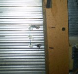
I have had to repair one of those loops that had opened up and rendered the bottom half completely dead, one time.
Henry,your projects inspire me very much!
Although I am working on ESL's at the moment,I did do alot of experimenting with this stuff back in the 90's and I have been thinking about lately of building some smaller desktop models as well.
I just need to get a new stockpile of magnets.
Keep on DIYing!!!!
jer")
I have had to repair one of those loops that had opened up and rendered the bottom half completely dead, one time.
Henry,your projects inspire me very much!
Although I am working on ESL's at the moment,I did do alot of experimenting with this stuff back in the 90's and I have been thinking about lately of building some smaller desktop models as well.
I just need to get a new stockpile of magnets.
Keep on DIYing!!!!
jer
Hey Jer, just got a pair of Duetta Sigs...the bass panels sounds OK and no rattles, so I guess I really lucked out!!
From the pics, it looks like you were able to remove the speaker assembly from the frame? I would not mind taking the frames and painting them piano black (frames are the worst part of the entire speaker).
Also think as long as I am in there, replace the tweeter ribbons - I think GRAZ will sell just the tweeter ribbons for a DIY install...do these appear to be a big deal?
I have yet to do any critical listening, but happy so far...
That is Great !!!!
The ribbons should be very easy to replace as they are just sandwich between a couple of blocks held in place with threaded holes and machine screws.
I never took them off so I don't know if there will be any glue involved making it difficult to take them apart and release the ribbon.
The Covers are held on by two screws at the bottom and the top is secured by a couple of Velcro strips.
So you must lay them down first in order to get the screws out and then it should lift right off starting from the bottom and then the velcros will peel off releasing the top.
On mine there is only two of them at the very top a little off from the center on each side.
If you need I can get some more pictures.
jer
Last edited:
Wow ...
That great on the Duettas...I had a pr in the 90s...But thay got a small buzz...Hart breaker...need i say more...
I well just stay with the stages...i can take the pain...yes you can get the tweeter-mid an do it yourself i know other that have...
An you can get a new bass an have it installed at your home...With NO moveing around get miny years if you ever get a buzz..
I say dont move them around if got them home an there not buzzing now...
good luck ..have fun...Apogges are Killer Speakers i think youll like them a lot!
Thanks guys, yes, I looked around and read that the frames are pretty easy to remove. Like I said, the frames were the worst part - sonically they are in great condition...I want to actively biamp with my DCX2496 and play around with them. The crossover appears to be a 1khz 6db slope....I need to unhook some passive xo wiring to get them active...getting excited!!
No required tension on the tweeter foil replacement? I think the originals are OK, just thinking of replacing as they appear easy to do...no real crimps or creases anywhere on tweeters and bass panels!
Although need another project like I need a hole in my head...
No required tension on the tweeter foil replacement? I think the originals are OK, just thinking of replacing as they appear easy to do...no real crimps or creases anywhere on tweeters and bass panels!
Although need another project like I need a hole in my head...
If the ribbons are good shape I would just leave them as they are.
They just rest on a bit of open celled foam, kinda like the Sonex stuff you use for wall treatments or packaging filler for shock absorption that it used for shipping hardrives.
Mine have long since dried up and withered away as dust.
I had had the schematic of the crossover somewhere in my archives but I think it still can be found on the web.
jer
Last edited:
......Lot of info here an schematic of the crossover an manuls for Duetta an most others...... Apogee Speaker Users Website
I have built an A4 design using 25 x 6 x 3 mm neos quite pleased with the outcome.Yes it is hard to tell because it is hidden by the frame.
I have had to repair one of those loops that had opened up and rendered the bottom half completely dead, one time.
Henry,your projects inspire me very much!
Although I am working on ESL's at the moment,I did do alot of experimenting with this stuff back in the 90's and I have been thinking about lately of building some smaller desktop models as well.
I just need to get a new stockpile of magnets.
Keep on DIYing!!!!
jer
Attachments
-
 SAM_0153.JPG502.9 KB · Views: 923
 -
 SAM_0170.JPG731.1 KB · Views: 228
 -
 SAM_0163.JPG703.2 KB · Views: 220
 -
 SAM_0162.JPG680.5 KB · Views: 215
 -
 SAM_0160.JPG675.5 KB · Views: 181
 -
 SAM_0159.JPG779.1 KB · Views: 198
 -
 SAM_0158.JPG682.9 KB · Views: 759
 -
 SAM_0157.JPG729.6 KB · Views: 805
 -
 SAM_0155.JPG409.1 KB · Views: 829
 -
 SAM_0154.JPG427.4 KB · Views: 866
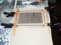
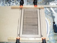
some more pics.
Have posted more pics on my own thread planars using neos.Vary cool...Henry...thanks for the piX
Hey all, I have a quick question - my Duetta Sigs have tweeter/mids panel and bass panel DC resistance 3 ohm / 3 ohm, while the other is 3 ohm / 8 ohm... one is obviously wrong...anyone know? I am thinking the 3/8 is correct, and there is a ribbon short going on in the 3/3...
Also, there was a Apogee speaker thread regarding repair from an olaf that has mysteriously dissapeared from apogee acoustics forum....don't have any buzzing issues yet, but would like to know what the DIY fix could be...
Thanks!!
Also, there was a Apogee speaker thread regarding repair from an olaf that has mysteriously dissapeared from apogee acoustics forum....don't have any buzzing issues yet, but would like to know what the DIY fix could be...
Thanks!!
On the one that I could get to, I measured 3ohms for the tweeter ribbon as well.
The woofer section has issues and it may be open again as it did quit working on me last time I had them powered up.
I did repair that one before and they have two sections to them it may be that one of the section are open as the are in parallel.
I had written it off as an amplifier issue and disconnected it and never check it or hooked them up again.
That was when discovered one channel of my amp was/is intermittent.
Later today I will unbury the other one and see if I can get a resistance reading from that one for you.
I do think that that one is in full working order.
Yes, I do remember those websites and they were very hard to find and alot of the threads that I have read have been deleted since the first time I had found them.
I believe that this was a politic type of issue with graz and people wanting to DIY/Fix there own units.
As many were doing a bad job at it and giving the product a bad name.
At least that was what I read in the forum.
jer
Yes, thanks Jer...
Hmmm, reading a technical review of the DS, it was mentioned that the bass panels was 3.8 ohm. Now I am thouroughly confused...it could be like you say, one section of the paralelled bass ribbon is out...
Something is not quite right, and looks like i need to open them up for a look...
Hmmm, reading a technical review of the DS, it was mentioned that the bass panels was 3.8 ohm. Now I am thouroughly confused...it could be like you say, one section of the paralelled bass ribbon is out...
Something is not quite right, and looks like i need to open them up for a look...
Yes the site is GONE!.....go fig all the old post are lost for ever...i had the site for 3 years an read an re read...but it lost so all is on the users fourm...but the only diy fix for buzz... i saw was to take fom tape an put it on the wood that frams the bass driver an let the fom go up a genst the bass driver... this well help remove some of the buzz...
i have a guy that begging to take a pr of Duettas ....my hart wont take it...never saw any of the biger than stages that dont all buzz sooner are latter....hope your never do...But...Thats just my ....good luck
i have a guy that begging to take a pr of Duettas ....my hart wont take it...never saw any of the biger than stages that dont all buzz sooner are latter....hope your never do...But...Thats just my ....good luck
I just got to the other panel it is open to !!!
The tweeter ribbon is down 1 ohm or so and reading about 1.9 Ohms by my meter.
All of my readings include the .3ohm offset of my probe resistance.
I don't know why this is, except that there are two aluminium strips on top of each other that complete the series loop of the three sections of the ribbon, and these two may be shorted together as there is no extra insulation to separate them.
Now for the woofer panels,
It appears the two sections are in series.
I got 2.9 ohms for the top section on one panel.
And 2.6 ohms for the bottom section on the other panel.
Also the lager air core inductor for the cross over is about .5 ohm.
Therefore the total resistance should be about 2.6+2.3+.5=5.4 ohms plus a little bit for the rest of the traces connections and wiring.
Both of the sections go the entire length of the panel and it may very well be possible that one of your sections is open and had been rewired for use of just one of the sections working.
Thus the reason for your 3 ohm measurement.
Back in 2000 I had to repair the one panel by using some wire warp wire glued on to the the diaphragm with some silicone and circuit works conductive silver paint.
And I guess I am going to have to do this again for the other section.
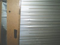
The other panel is going to be a bit more involved as it has a line of micro cracks in the aluminium voice coil all of the way down the panel on both sides were it was slapping against the edge of the magnets that are in the back of the diaphragm.
I was crankin' on them pretty hard that day as they were trying to keep up with my 4 X 10's and 4 X 12's woofer system.
They made for a very nice and clean midrange system that day for a little while!! he,he,he,he
Luckily I wasn't using the ribbons then!!
But at least they are repairable though.
I will try to get to them maybe this summer once I get some room made to properly set them up again.
jer
The tweeter ribbon is down 1 ohm or so and reading about 1.9 Ohms by my meter.
All of my readings include the .3ohm offset of my probe resistance.
I don't know why this is, except that there are two aluminium strips on top of each other that complete the series loop of the three sections of the ribbon, and these two may be shorted together as there is no extra insulation to separate them.
Now for the woofer panels,
It appears the two sections are in series.
I got 2.9 ohms for the top section on one panel.
And 2.6 ohms for the bottom section on the other panel.
Also the lager air core inductor for the cross over is about .5 ohm.
Therefore the total resistance should be about 2.6+2.3+.5=5.4 ohms plus a little bit for the rest of the traces connections and wiring.
Both of the sections go the entire length of the panel and it may very well be possible that one of your sections is open and had been rewired for use of just one of the sections working.
Thus the reason for your 3 ohm measurement.
Back in 2000 I had to repair the one panel by using some wire warp wire glued on to the the diaphragm with some silicone and circuit works conductive silver paint.
And I guess I am going to have to do this again for the other section.
The other panel is going to be a bit more involved as it has a line of micro cracks in the aluminium voice coil all of the way down the panel on both sides were it was slapping against the edge of the magnets that are in the back of the diaphragm.
I was crankin' on them pretty hard that day as they were trying to keep up with my 4 X 10's and 4 X 12's woofer system.
They made for a very nice and clean midrange system that day for a little while!! he,he,he,he
Luckily I wasn't using the ribbons then!!
But at least they are repairable though.
I will try to get to them maybe this summer once I get some room made to properly set them up again.
jer
Attachments
Last edited:
I was thinking the 3 ohm bass panel was functional, and there are two paralleled 8 ohm bass panel traces equalling 3.8 - 4 ohms total (and one trace out), but you say there are two 3 ohms in series indicating closer to 8 ohms probably the functional one?
I am confused...also, I am taking my readings with no passive xo - bass panel is black wire to red wire, and trwweter mid from brown wire to blue wire (these are the heatshrunk covered wires for active baimping, circumventing the passive XO components)
I am confused...also, I am taking my readings with no passive xo - bass panel is black wire to red wire, and trwweter mid from brown wire to blue wire (these are the heatshrunk covered wires for active baimping, circumventing the passive XO components)
- Home
- Loudspeakers
- Planars & Exotics
- Apogee Speakers Construction