The toroidal high frequency transformer for the CLX has 4 taps so it may well be used in several other ML models. The Fet board in the CLX has a more sophisticated circuit than the Fet board shown in post 24 and has no power diodes. if the ribbon cable from the power supply board isn't connected to the Fet board it doesn't pass an audio signal except a hf signal through the 0.33 uf bypass caps. I'm assuming (guessing) it gets both power to turn it on and a gate signal from the power supply board which first senses the audio signal from the input side of the Fet board. I should have a further look at the Fet board because if it's just a progressive power limiter i'll try bypassing the power fets as i run a 200 watt Borbely class A power amp in an old Krell KSA 100 chasssis on it, plenty loud enough for me. I should trace it out to make a more correct comment on it's function - if only I could put the Patron down and get Junior Wells off the turntable.................
I believed the Fet board was there for gating the audio signal to avoid driving the transforemers/cells when no bias voltage was present. I can understand the 0.33 bypasses on the HF side fets , but not sure why they are there on the LF Fets - ML used cheap box type metalised film caps in any case and they all got replaced with MIT film and foils.
I believed the Fet board was there for gating the audio signal to avoid driving the transforemers/cells when no bias voltage was present. I can understand the 0.33 bypasses on the HF side fets , but not sure why they are there on the LF Fets - ML used cheap box type metalised film caps in any case and they all got replaced with MIT film and foils.
Last edited:
Hello ticknpop,
Thanks for sharing information with us all about your CLX.
There is so little technical information on it available, every little bit is very helpful.
I know that their Statement II mentions such adjustments in their user’s manual. I don’t remember seeing any in the CLX manual.
As always, photos will help figure things out.
If used as a safety switch in series with audio, would be interested to know the ON resistance of the FETs as this would affect the HF response. What is the part number on the FETs?
BTW, I recently learned that Dayton Wright used a large safety relay in series with the audio.
Ok, final question…are there any other circuit boards in the CLX that contain FETs?
Perhaps it has both a safety switch and a limiter like their other products.
Thanks for sharing information with us all about your CLX.
There is so little technical information on it available, every little bit is very helpful.
It is possible that they are there as part of an adjustable response EQ based on your listening distance.The toroidal high frequency transformer for the CLX has 4 taps so it may well be used in several other ML models.
I know that their Statement II mentions such adjustments in their user’s manual. I don’t remember seeing any in the CLX manual.
For a full range limiter the diode bridge would need to be able to handle much more power than the 3A single diodes in the SL3 hybrid limiter. Is it possible that some of what you think are FETs on the heat sinks are in fact high power diodes? If you have already confirmed that all four heatsinked parts are FETs, then you would need to trace out the audio circuit like you suggested to determine if they are used in series with the audio as a safety switch like you suggest, or possibly in shunt across the transformers as a progressive limiter. It is very common to drive back-to-back FET switches with a photo-voltaic isolater. Are there any small 8 pin ICs on the FET board?The Fet board in the CLX has a more sophisticated circuit than the Fet board shown in post 24 and has no power diodes. if the ribbon cable from the power supply board isn't connected to the Fet board it doesn't pass an audio signal except a hf signal through the 0.33 uf bypass caps. I'm assuming (guessing) it gets both power to turn it on and a gate signal from the power supply board which first senses the audio signal from the input side of the Fet board.
As always, photos will help figure things out.
If used as a safety switch in series with audio, would be interested to know the ON resistance of the FETs as this would affect the HF response. What is the part number on the FETs?
BTW, I recently learned that Dayton Wright used a large safety relay in series with the audio.
Ok, final question…are there any other circuit boards in the CLX that contain FETs?
Perhaps it has both a safety switch and a limiter like their other products.
The audio input signal into the CLX comes in on a single pair of binding posts (
ML used impressive looking ones that easily break because they are crap) - I changed to WBT platinum signatures). The signal goes to 2 crossover boards 1 low frequency 6 db/oct board with switch selectable series resistors to adjust the LF level and then the LF signal goes to the Fet board. The high frequency filter board has 3 air core chokes and 4 caps ( 33uf, 2 x 22 uf, and 1.5 uf). One choke and the 1.5 uf cap appear to be a notch filter. Then the HF signal goes to the Fet board too. There are 2 IRF 640 fets back to back on each of 2 large heatsinks ( i put taller heatsinks in). There are no ic's on this fet board, just a couple of T0 92 small signal transistors. The positive and negative signal each goes through a 640 fet and then is connected to it's transformer's input. ( EI for the low end and torroidal for the HF - no taps on the LF transformer , but 4 taps on the HF primary - i suspect a common transformer used for all the bigger ML hybrids, just select the tap for the set they built each time.
I believe the audio signal is sensed on the fet board and tells the power supply board to turn on and this in turn powers the drive signal to the IR 640's - if the ribbon cable connecting the fet board to the power supply board is unplugged the fet board does not work and will not pass the audio signal except throught the 0.33 uf caps which bypass the IR 640s.
No other power fets or clamp boards
I'll take the cover off the interface tomorrow and take a few pictures.
However the fet board is under a board ML used to mount terminals and connectors fromthe transformers to the cells to make building and service easy which my DIY evil self hardwired and used the space for MIT crossover caps to replace the Solens ML used. That's one I can't figure out - it gets great reviews for midrange resolution through $30 worth of caps - it really improves a good deal with the MIT PPFXS and RTX upgrade and is night and day more resolving - so only the overbeveraged friends at my place have heard what a CLX can really do ( and i added a Raven ribbon to them - soon to be RAAL - the upgraded CLX top end is nice but no where near as resolved as with the ribbon. It strikes me that all the argument about which amp to use on them is rather wasted through the mediocre grainy, compressed signal caps ML used
Last edited:
I also have 5 pairs of Dayton Wrights XG 8 , XG 10, XG 10 mk 2 in the garage ( 2 working pairs ) with lots of parts, tank of SF 6 , DW subs etc all to sell off this fall. The relay was in series withe audio signal and wouldn't close unless the AC to the bias supply was present (A simple way to prevent driving the system without bias present)
And a pair of Quad 63's that i hand carried over to Huntington for a complete rebuild years ago and still have them in thier boxes downstairs for over a decade, a set of ML Requests in the front hall to pass on to a friend and rebuilt Acoustat model 1's on my computer. Too many electrostats and too little time.
And a pair of Quad 63's that i hand carried over to Huntington for a complete rebuild years ago and still have them in thier boxes downstairs for over a decade, a set of ML Requests in the front hall to pass on to a friend and rebuilt Acoustat model 1's on my computer. Too many electrostats and too little time.
Last edited:
hello again ticknpop,
Thank you for taking the time to trace out the CLX circuits and describe them in detail. I look forward to the pics. Interesting to hear about the easily breakable binding posts. I had always thought they looked rather robust from the brochure pictures.
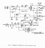
As you mentioned, the Dayton Wright XG-10 did have a relay in series with the audio signal going the step up transformers.
Looking at the attached schematic, you can see that the relay will be energized if and only if two things happen:
1) 120VAC wall power is applied
2) The safety interconnect switch is closed.
My guess would be that this relay was to make sure a customer didn’t accidentally have audio applied to the step-up transformers when he/she had the interface box open and could accidentally touch some wires carrying the high current High Voltage coming from the secondary of the step-up transformers. I good safety precaution I would think.
This setup would also keep a user from inadvertently turning up the volume to much if the HV supply was not plugged in and they didn't hear much sound coming from the panel and just kept turning up the volume. They could potentially overdrive the transformers or arc the panels. Perhaps this is the purpose of the FET switches in the CLX as well.
Thank you for taking the time to trace out the CLX circuits and describe them in detail. I look forward to the pics. Interesting to hear about the easily breakable binding posts. I had always thought they looked rather robust from the brochure pictures.
As you mentioned, the Dayton Wright XG-10 did have a relay in series with the audio signal going the step up transformers.
Looking at the attached schematic, you can see that the relay will be energized if and only if two things happen:
1) 120VAC wall power is applied
2) The safety interconnect switch is closed.
My guess would be that this relay was to make sure a customer didn’t accidentally have audio applied to the step-up transformers when he/she had the interface box open and could accidentally touch some wires carrying the high current High Voltage coming from the secondary of the step-up transformers. I good safety precaution I would think.
This setup would also keep a user from inadvertently turning up the volume to much if the HV supply was not plugged in and they didn't hear much sound coming from the panel and just kept turning up the volume. They could potentially overdrive the transformers or arc the panels. Perhaps this is the purpose of the FET switches in the CLX as well.
Attachments
The hole in the original CLX post to mount bare wire weakens it so that if you tighten it too much with a large bare wire the post breaks. After doing this twice and seeing the original posts aren't great replacing them with the original posts is a waste of time. I changed them to something more substantial, but this was a little trickey as you need a 90 degree drill chuck to widen just the rear portion of the mounting holes - depends on which post you use - WBTs are too large for the existing holes.
I'm not sure if the Dayton Wright relay was done to protect the cells from an unbiased audio feed or as part of the safety interlock with the front panel AC lockout - probably helped both functions. The Hammond EI core stepup transformer for each speaker weighs 39 pounds with an 80k secondary - the entire interface unit weighs over 100 lbs
I'm not sure if the Dayton Wright relay was done to protect the cells from an unbiased audio feed or as part of the safety interlock with the front panel AC lockout - probably helped both functions. The Hammond EI core stepup transformer for each speaker weighs 39 pounds with an 80k secondary - the entire interface unit weighs over 100 lbs
Last edited:
ribbon and clslla
Tick and Pop, I have a pair of Decca ribbon supertweeters. Used them with my Quad ESL 57,s. Can I use them with my clslla? The clslla has a 5N 10Kcap in the panel to ground, I believe it is mylar not polyprop. Would changing this cap to a higher capacitance and better quality make a difference?
Tick and Pop, I have a pair of Decca ribbon supertweeters. Used them with my Quad ESL 57,s. Can I use them with my clslla? The clslla has a 5N 10Kcap in the panel to ground, I believe it is mylar not polyprop. Would changing this cap to a higher capacitance and better quality make a difference?
The 5N cap - that 5n value sounds more like a power supply cap or RF filter so changing it will likey not change the sound.
Adding the tweeter is fine, but how would you mount them? I have the Ravens hung at ear height on fishing line behind the curved cell of the CLX so nothing is damaged or drilled and easy to remove. I built a curved piece of metal that is just larger than the gap between the cell and the frame to hang the tweeter right up next to the cell - you don't want it hanging back. Yes i'm sure there is interference with the cell hole pattern, but it works remarkably well.
Adding the tweeter is fine, but how would you mount them? I have the Ravens hung at ear height on fishing line behind the curved cell of the CLX so nothing is damaged or drilled and easy to remove. I built a curved piece of metal that is just larger than the gap between the cell and the frame to hang the tweeter right up next to the cell - you don't want it hanging back. Yes i'm sure there is interference with the cell hole pattern, but it works remarkably well.
The numbers from the Zener Z1 on my MLDEC-4 board:My limiter uses exactly the same circuit as the ML Dec-4. Full range or hybrid operation does not change the operation of the limiter. The only possible difference would be what the voltage threshold is for the limiter to start working. The MOSFET in the limiter will only get hot when the input voltage exceeds the voltage threshold set by the zener diode. Mine does not get hot at all unless I use an amplifer > 300W/8ohm.
If you say your SL3 limiter gets hot with most any input, then ML must have set the voltage threshold for activating the limiter quite low. We will wait to see what part number Andersonix pulls of the zener diode in his limiters.
759
A
1N4
Bolserst
The MOSFET in the limiter will only get hot when the input voltage exceeds the voltage threshold set by the zener diode. Mine does not get hot at all unless I use an amplifer > 300W/8ohm.
Jim Powers at ML did not like the turm Limiter....But i sead that what this dose is run my $5k amp...Thought this 5.Cent diodes Bridg an into this $40cent fet ....that eats the power coming in...so it pulles power a way...like a limiter.. he sead yes...but you can pull it out.. if you dont like the sound...So now you say it well not have a sound of it owen.. i say if it hot are not it riding on the amps output...an if it out you can here if you are over driving the panel...the sound is much better with it out i find... all i can see it doing is Mybe saving someone from over driving there panel...but if this limiter is pulling power away The over driver, person is just going to turn it up more...
Out...I see this as less is more.
Thanks
The numbers from the Zener Z1 on my MLDEC-4 board:
759
A
1N4
Thanks!
With that Zener diode(1N4759A = 1W 62V) the MLDEC will start limiting at about 275W into 8ohm.
Most people using 100W - 200W amplifiers will never even activate the limiter.
if it out you can here if you are over driving the panel...the sound is much better with it out i find... all i can see it doing is Mybe saving someone from over driving there panel...but if this limiter is pulling power away The over driver, person is just going to turn it up more...
This is true that with the limiter out somebody might more easily notice if he is overdriving the panel and turn the volume down.
But, I think the main purpose of the limiter is to prevent the generation of ozone, and thus prolong the life the of diaphragms and stators.
Ozone isn't exactly good for human consumption either.
I have found many times I was driving my ESLs hard enough to generate ozone and didn't notice any distortion that would have clued me in to turn down the volume.
With the limiter hooked up, this isn't a problem.
You are right on the money...on the o-zone...but...the limiter, jim at ML an i agread was there for a 50w cliping amp....to eat the clip...dc..an ac...being domp on the panels...it not hard to clip a amp with MLs..so on paper it looks like what you are saying, but not realy.....if like most audiopiles you have a good amp...less is more here..it on the outputs of any amps...it cost$1....not on my amps...on yours are fine...these have 10-12"bass drivers the limiter is not on the bass ...i have siad the a full rang ESL can benafit from the limiter..less tranfourmers sataion.. i brot this up.... but i well never say to anyone in audio that you cant here it .... it on the output all the time, runing in to the diods..at a 1/2 w...why say oh you can hear it...Your saying you can hear it till it truns on...An then your say you can hear it...i can hear most thing an so can other...say it eze to take out an put in, one wire..an if you dont hear a diff leve it out ... are put it in if it make you feel better....less your sale them??
i well tell you i have 4 pr of ML here now an i can here it in all of them!
i well tell you i have 4 pr of ML here now an i can here it in all of them!
- Status
- This old topic is closed. If you want to reopen this topic, contact a moderator using the "Report Post" button.
- Home
- Loudspeakers
- Planars & Exotics
- Martin Logan SL3 crossover