It sounds like you are well-informed on horn theory. So here is my question: ignoring the rear sealed box or adjusting its size accordingly and ignoring all other practical issues, wouldn't driving a horn with an ESL result is very good impedance match?It isn't going and never will!. If I recall correctly I think it was Baxandall who pointed out in his writings on ESL's that the motor strength generated by an ESL is around 1/40th that of a moving coil motor.
When we achieve a good impedance match to the air with a horn the driver has to do some serious work. The (acoustic) load has a dominant real part (as in real and imaginary, when describing complex impedances) ESL's are found lacking when loaded in this way and the addition of a rear chamber will only make matters worse. Analogous to electrical power, acoustic power is the product of pressure and particle velocity. It is in the pressure department that weak motors tend to stall.
Keith
Thanks.
Ben
The horn will provide a good impedance match, but the ESL as a driver will not be able to fully exploit it. Maybe an electrical analogy would be a low powered generator that is lightly loaded. Sure, it outputs an acceptable voltage, but what happens when we want to load it more heavily to get more current? The thing is that power is the product of voltage and current and not current or voltage alone.
What I am suggesting is that our weak motor in the ESL can move the membrane when it is loaded with a thin boundary layer of air and create some particle velocity. When we need some pressure also, as in the throat of the horn, the motion cannot be sustained.
I am not an expert on horns, or anything for that matter but I do like helping others understand things that are not normally mentioned in the same sentence such as ESL's and horns. Of course we are very much in the realm of acoustics and one often mentioned phase in acoustic textbooks is "freely propagating waves"
In space re electromagnetic waves, the medium has a characteristic impedance of 770 odd Ohms. How do we know this? R=E/I. If measure the voltage with a field intensity meter and the magnetic field with a loop arial? we can extrapolate the impedance that is giving rise to this particular ratio.
Likewise air has a characteristic impedance of around 300 acoustic Ohms, something that can be verified by measuring pressure and particle velocity at the same point in space.
As for sources we can have "pure" pressure transducers (sealed box) and pure velocity transducers (dipole). Obviously, up close to the diaphragm we have one missing element, the velocity element for the pressure source and the pressure element for the dipole source. As the waves travel away from these sources and become freely propagating the missing elements get added. When the source is matched to the surrounding medium/air we have the correct relationship between pressure and velocity from the start so our whole system becomes more efficient power wise.
Sorry to be mentioning things you may already know.
Keith
You don't need to be an expert on horns to be right. There is much to little motor force in a standard ESL configuration for horn loading to be effective.
The patent idea above is a sort of compound method. But if it worked it probably would have seen production.
Horns are not a solution in every application.
The patent idea above is a sort of compound method. But if it worked it probably would have seen production.
Horns are not a solution in every application.
You can get some very nice forces acting upon the diaphragm at much higher voltages than your typical ESL design.
I have used as much as 10Kv of bias and higher although this kind of range does introduce its own set of problems.
I now have a much better understanding of the opration horns and the ESL as well.
I have found that careful sizing and/or segmentation (physical and/or electrical) produces the desired result of widening the horizontal dispersion of an ESL.
However I will still try the horn loading technique sometime just to see what the effects really are.
I just need to finish my latest driver design, as all that is left is to mount the diaphragm.
This next design will/should handle up to about 14Kv of bias with out arcing and destroying itself or burning the diaphragm.
I have been working on transformer and amplifier related issues lately.
As I want to repeat my original test of running 10kv of bias and +20Kv p-p across the stator's without any breakdown issues.
It is just a hobby and sometimes I get burned out from the intense research and I have to take a break every once in a while, So I am just plain slow at it (He,he,he,he).
I have measured as much as +120db at the diagphram on my last panel so I don't think there is an issue of not having enough forces acting upon it.
But, There may very well be an impedance matching issue due to the very low mass (lighter than air) of the diaphragm itself to overcome the extra loading of the air mass at the throat of a horn.
In past experiments I have noticed a bit of change (lowering) in the quality of sound just by having some loose Fiberglass insulation within a 6" proximity of the diaphragm from the back of the panel in attempt to reduce the backwaves dipole cancelling effect.
I am not sure if this was caused by reflections of the fiberglass canceling the wavefront through front of the diaphragm, or, if it was actually a loading mismatch of the increased pressure behind the diaphragm due to the semi closed area?
I was just getting back into this at the time and I didn't spend a whole lot of time on it as I wasn't happy with the results to begin with.
The loading caused a drop in high end detail it was noticeable but wasn't significant as far as the frequency response was concerned.
It sounded like plain ole dynamic mid/tweeter than having the finesse of an ESL.
As soon as I removed the fiberglass to at least a foot away, the magical sound of the ESL had been restored.
Also I was using just one panel at the time (mono) so I don't know how much it could have effected the stereo imaging.
However, Adding the extra distance around the panel did increase my low end response curve by about +3db as expected.
jer")
I have used as much as 10Kv of bias and higher although this kind of range does introduce its own set of problems.
I now have a much better understanding of the opration horns and the ESL as well.
I have found that careful sizing and/or segmentation (physical and/or electrical) produces the desired result of widening the horizontal dispersion of an ESL.
However I will still try the horn loading technique sometime just to see what the effects really are.
I just need to finish my latest driver design, as all that is left is to mount the diaphragm.
This next design will/should handle up to about 14Kv of bias with out arcing and destroying itself or burning the diaphragm.
I have been working on transformer and amplifier related issues lately.
As I want to repeat my original test of running 10kv of bias and +20Kv p-p across the stator's without any breakdown issues.
It is just a hobby and sometimes I get burned out from the intense research and I have to take a break every once in a while, So I am just plain slow at it (He,he,he,he).
I have measured as much as +120db at the diagphram on my last panel so I don't think there is an issue of not having enough forces acting upon it.
But, There may very well be an impedance matching issue due to the very low mass (lighter than air) of the diaphragm itself to overcome the extra loading of the air mass at the throat of a horn.
In past experiments I have noticed a bit of change (lowering) in the quality of sound just by having some loose Fiberglass insulation within a 6" proximity of the diaphragm from the back of the panel in attempt to reduce the backwaves dipole cancelling effect.
I am not sure if this was caused by reflections of the fiberglass canceling the wavefront through front of the diaphragm, or, if it was actually a loading mismatch of the increased pressure behind the diaphragm due to the semi closed area?
I was just getting back into this at the time and I didn't spend a whole lot of time on it as I wasn't happy with the results to begin with.
The loading caused a drop in high end detail it was noticeable but wasn't significant as far as the frequency response was concerned.
It sounded like plain ole dynamic mid/tweeter than having the finesse of an ESL.
As soon as I removed the fiberglass to at least a foot away, the magical sound of the ESL had been restored.
Also I was using just one panel at the time (mono) so I don't know how much it could have effected the stereo imaging.
However, Adding the extra distance around the panel did increase my low end response curve by about +3db as expected.
jer
Nice to see your horn experiments proceeding.
Funny, a few times I've read about people putting stuffing behind ESLs and I glued together meter-square panels of acoustic fiberglass board I made for that purpose too.
The theory (we must destroy the unengineered rear wave bouncing aimlessly around the back walls) seems right. But now Gerald can be added to the list of folks who found it was harmful to do so.
I think it is one more vote of support in Toole's argument that ambiance of speaker sound is a top criterion. And one more reason the familiar simulation models leave much out.
Ben
It wasn't so much as destroying the rear wave was the problem as this was a good thing,especially since the experiment was performed on my desk that has lots of cavity's that causes a few dips and peaks to the response.
But the loading up of the diaphragm (as others have asked "what happens if you put it in a box or stuffed the back of it") seemed to have the most profound and detrimental effect.
I don't have any photos of that particular experiment setup but I think there my be one or two in another thread somewhere.
jer
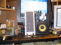
Attachments
Last edited:
jer,
The white cell in the previous post looks very similar to the JanZen design, later used by RTR...
I assume the closed squares around the periphery are glued on plastic?
The JanZen cells actually were glued between columns of squares making long thin parallel strips of diaphragm...
The white cell in the previous post looks very similar to the JanZen design, later used by RTR...
I assume the closed squares around the periphery are glued on plastic?
The JanZen cells actually were glued between columns of squares making long thin parallel strips of diaphragm...
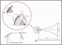
The ESL driven horn you refer to is not a simple case of horn loading an ESL panel. Rather, it is showing you how to get around the ESL loading limitation using a prisimatic wave guides to drive the throat of the horn with an ESL having an area 10 to 15 times larger than the throat.Except that a very good, working, ESL driven HF horn was built and documented decades ago and is available to read in JAES Audio Anthology Vol 1.
More details/links back in post#8.
http://www.diyaudio.com/forums/planars-exotics/190023-horn-loaded-electrostatic.html#post2591288
There are two issues particular to ESLs that seem to be getting mixed together.
1) As Keith Taylor pointed out, ESLs have an inherently weaker motor system than dynamic drivers. But this in and of itself does not make ESLs unsuited for horn loading. If you reduced the magnetic field strength or signal voltage of a dynamic driver by a factor of 40 it would still benefit from horn loading, showing the same sensitivity boost ratio as before.
2) Except at the top of the bandwidth, the load the weak ESL motor has to drive is completely dominated by the airload. This is why it is unsuited to directly driving a horn, not because the ESL motor is weak. By comparison, the magnetic motor drives a load that is dominated by the mass of the cone and voice coil assembly. Increasing the airload by a factor of 10 has almost no effect on the total load it is driving. The same 10 fold increase in airload on an ESL would result in a 10 fold increase in total load the ESL motor has to drive and result in the diaphragm motion being reduced by a factor of 10.
This concept may or may not have been conveyed with more clarity in post#93:
http://www.diyaudio.com/forums/planars-exotics/190023-horn-loaded-electrostatic-10.html#post2613309
Attachments
Bear, The white plastic is just Plastic lighting grate that was used as support for the stator a common material used be many, Acoustat, Janzen and even Quad, etc.
The stator itself is flat as is the diaphragm.
It has no intended function except as support structure.
It is about 3/8" to 1/2" deep so any prismatic effect it may have will be well above the audio band.
Bolserst, The statement in 1# was basically what I was trying to convey.
In 2# you mentioned the mass of the cone and voice coil assembly and this how I understand it as well.
My point is that some of this can be compensated by using higher drive and bias voltages.
But the question remain's, Will there be any benefit and how much from a horn loaded ESL due to the size of the apparatus as a whole and would I have to use a higher mass (thicker)diaphragm in order to see any gain.
If so then how much high frequency efficiency will be lost due to the higher mass diaphragm.
All else I do understand the concept more so than I did when I first had the idea.
jer
I did a test many years ago, not without deficits in the set up, but a considerable amount of work went into it.
I took a standard Acoustat 9" or 8" 4 foot high cell and fabricated two exponential curves, one for each side of the cell... exactly the same height as the cells. The cells were fastened to the rear of the horn curves, left and right. The combination stood on the floor. flat wood cover on top.
The flare and mouth size was suitable for 300 hz., notwithstanding the height, which might have lowered the lowest freq. Dunno how that ought to work.
Problem was I could detect no benefit, no particular change in the response, by ear. At that time I had no accurate means to check the freq response... but there was nothing audible that screamed "test my frequency response".
I abandoned that approach.
Good question.
My recollection was that it had no beneficial effects. Which was dismaying after all the work that went into fabricating these two big curvy things.
I would have expected some difference in the way that some frequencies "bounced" off the sides, but I don't recall noting this. I may have not really taken note, since the main effect, a boost somewhere in the frequency response was not found.
You could do a preliminary test with just two flat boards of sufficient size, they being a "conic horn" and pretty easy to set up.
My sense of it is that the highs are much more beamy than people think on a typical ESL. I've taken my Acoustats in years past outside for a listen, and they are stunningly beamy, and the highs do not extend off axis!! It's the ambient reflections in the room that give the sense of decent of axis HF response in the main. If you haven't tried outside with some ESLs, ur in for a big surprise there. Shows instantly the effects of the room.
I kept meaning to go back and try to clarify this point concerning horn loading an ESL since things had gotten kind of sidetracked while discussing the sensitivity issues of the ESL itself. No losses are happening when horn loading an ESL at mid and lower frequencies. The SPL will be essentially the same with or without the horn.
Suppose you are driving an ESL panel such that the SPL @2m is 90dB. Then you add a horn that increased the airload on the ESL by a factor of 10. The result would be that the ESL diaphragm would now move with only 1/10th the amplitude it had been before the horn was added. But, the horn now couples this smaller motion to 10 times the area of air. The end result would be an SPL @2m still pretty darn close to 90dB.
In the case of a dynamic driver, when the horn is added the amplitude of the cone motion isn’t reduced much at all since the added airload is not significant compared to the mass of the cone. Therefore the acoustic output is increased by the ratio of the horns output and input areas. By making the throat smaller than the driver diameter(sometimes called compression loading) it is possible to increase the airload on the driver to the point that it starts to reduce the amplitude of the cone motion. This technique yields maximum efficiency from the driver. Reducing the throat diameter beyond this point and you run into the same situation you have with an ESL and you gain no further increase in output.
If you are familiar with compression loading and horns, perhaps this simplified comparison will make the ESL case make sense to you.
Been reading through this thread learning a bit and a thought occurred to me when I read this post. Still have 4 pages to go so if someone else picked up on this thought before I get through, my bad
Since the horn would limit movement of the diaphragm wouldnt that help to increase sound quality as that is directly tied to reactivity of the diaphragm? For dynamic drivers this is a large consideration anyways, so I would think for ESL's this should be a multiplicative effect as the ESL force changes based on distance of the diaphragm from the stator more so than that of a dynamic driver.
Hm, my reply didnt seem to work, guess I will try again.
Since the diaphragm movement would be limited wouldnt this result in a sound quality gain? There may be no discernible SPL output but I would think the reduction in distortion due to less movement of the diaphragm would be welcomed.
Now another aspect i'm looking at is the force applied to the diaphragm with relation to its position between the stators. Is force constant across the gap or does it change relative to the position of the diaphragm?
ok, sorry for triple post but need to poke this one in too. First post (#134) can be disregarded as I learned more between posting that and the second one
Has anyone tried use a 3-layer (conductor|insulator|conductor) diaphragm to allow using the diaphragm as also a stator? In theory this should act somewhat as a dipole setup significantly increasing available motive force?
Has anyone tried use a 3-layer (conductor|insulator|conductor) diaphragm to allow using the diaphragm as also a stator? In theory this should act somewhat as a dipole setup significantly increasing available motive force?
Has anyone tried use a 3-layer (conductor|insulator|conductor) diaphragm to allow using the diaphragm as also a stator? In theory this should act somewhat as a dipole setup significantly increasing available motive force?[/QUOTE]
Yep done it, makes no difference in the SQ or sensitivity.
Adding a second conducting layer on the opposite side of the diaphragm imposes a whole another set of issues, should one side lose contact it can become oppositely charged from the other side rendering no forces acting upon the membrane and having a dead panel.
Been there done that, it is already hard enough to get one good coating let alone two.
Not to mention that the added extra mass can give as much as a -.5db to -2db of extra roll off on the extreme high end !
As far as THD vs Diaphragm movement, ESL's typical are inherent from THD in their natural form, any THD that is introduced is strictly caused from the electronics driving them, except for of course excursion limited factors.
Trust me the thing will be way too loud before any of those limts are reached if built properly
Cheers !!
jer
P.S. I still want to give this a try for some Highpower PA use where the focusing of the gain by a horn may be if some use.
Tailoring of High Frequency horizontal dispersion is simply controlled with electrical segmentation for normal use.
As a thought, It may be also be possible to adjust for any front to back impedance mis-loading to the load (air) by introducing some asymmetrical diaphragm spacing, if it becomes an issue or is measurable in THD (should be/there is a thread on this).
Last edited:
" For dynamic drivers this is a large consideration anyways, so I would think for ESL's this should be a multiplicative effect as the ESL force changes based on distance of the diaphragm from the stator more so than that of a dynamic drive"
This effect is cancelled out as both stator's are driven out of phase of each other, However an ESL can also be driven single sided and in which case this would be an issue.
jer
This effect is cancelled out as both stator's are driven out of phase of each other, However an ESL can also be driven single sided and in which case this would be an issue.
jer
Getting an impedance match between the air and the driver is the pot of gold at the end of the rainbow. That's why cone drivers will never make it to audio heaven.
ESLs get close to matching, I suppose, but I've often wondered how they would sound with a horn to make the impedance match perfect. Why not?
B.
ESLs get close to matching, I suppose, but I've often wondered how they would sound with a horn to make the impedance match perfect. Why not?
B.
- Status
- This old topic is closed. If you want to reopen this topic, contact a moderator using the "Report Post" button.
- Home
- Loudspeakers
- Planars & Exotics
- Horn loaded electrostatic ??