Hello,
I am shortly before construction of my first ESL's. 4 pieces toroidal transformers 230V/3V, the high voltage cascades as kit, Mylar, Elvamide, tesa 4970 and ABS sheets 3mm (as spacer) are already available. The order for copper strip and series resistors is pending.
But selection and source of suitable high-voltage resistors for the low-pass segmentation and choosing a wire with suitable insulation thickness for the wire stator gives me a headache...
To determine the breakdown strength of the wire insulation, I took the following assumptions:
- At the diaphragm/membrane is a max. Bias of +5 kV.
- The max. amplifier output voltage is +-30V.
- 2 per ESL toroidal transformers are parallel wired at input side and in series at output, bringing the total effective transmission ratio of 1:136 (efficiency of transformer is about 0.89):
this results per stator in a maximum voltage of 68 x 30 V = 2.04 kV, but as the ESL is “acting” like a capacitor, the "DC equivalent" has to be calculated with U[peak] = U * square root (2), which results in about 2.9 kV as the maximum given voltage on a stator.
- With maximum membrane deflection/move - when the (positively charged) membrane is nearest to the (negatively charged) stator - therefore the voltage difference is between +5 kV - (-2.9 kV) = 7.9 kV
If my analysis was right up to this point, this would mean a wire isolation with electric strength of 8 kV would have to be considered. But this surprises me, as various DIY ESL stators are made of PU spray coated perforated sheet metal or PVC insulated jumper wire only.
Now I got in a forum the following point of view:
"If the charge is constant, and d is changed, then also C is changing, hence the voltage, too."
"Take for instance on both sides a distance of 2 mm and the membrane itself is moving 1 mm in one direction, then to this side the capacity is doubled and thus halves the voltage. On the other side the distance is increased from 2 to 3 mm, the capacity hence dropped to about 2 / 3 and increased the voltage to 1.5 times."
This derivation is likely based on the following formula for a capacitor connection:
U = Q/C = E*d = (Q*d)/(ε0*εr*A)
At constant charge and constant surface therefore the voltage U between the "capacitor plates" stator and membrane depends linearly on the distance d between the plates.
That would mean now that for a d/s of 3.5 mm (distance between the membrane and the conductive material of the stator) and just before the membrane hits the insulating layer (at about 3 mm displacement), of the bias voltage 5 kV only 14.3% (= 0.71 kV) would remain.
The electric strength of the stator insulation therefore could be designed for 2.9 kV + 0.71 kV = 3.61 kV only.
Is this assumption and calculation correct? Or do I have to design with 8 kV max voltage difference? My electro-technical understanding is unfortunately not very well, so I hope to get some comments of the specialists here
Thanks in advance...
Ur thinking too hard...
Afaik the bottom line relates to the conductivity of the diaphragm. If it is sufficiently high then you don't need much if any insulation on the stators... of course sharp edges or points are a no-no...
You can read back in one of the threads on the Acoustat, Andy Szabo specs the insulation of the Acoustat stator wire...
Moray James or Calvin can likely give you a precise answer depending on your construction method.
I'm hardly the expert on this matter...
_-_-bear
Hello,
I am shortly before construction of my first ESL's. 4 pieces toroidal transformers 230V/3V, the high voltage cascades as kit, Mylar, Elvamide, tesa 4970 and ABS sheets 3mm (as spacer) are already available. The order for copper strip and series resistors is pending.
But selection and source of suitable high-voltage resistors for the low-pass segmentation and choosing a wire with suitable insulation thickness for the wire stator gives me a headache...
To determine the breakdown strength of the wire insulation, I took the following assumptions:
- At the diaphragm/membrane is a max. Bias of +5 kV.
- The max. amplifier output voltage is +-30V.
I assume you mean 30VRMS so this will be 42volts peak-always use peak voltage when estimating worst case.
- 2 per ESL toroidal transformers are parallel wired at input side and in series at output, bringing the total effective transmission ratio of 1:136 (efficiency of transformer is about 0.89):
this results per stator in a maximum voltage of 68 x 30 V = 2.04 kV, but as the ESL is “acting” like a capacitor, the "DC equivalent" has to be calculated with U[peak] = U * square root (2), which results in about 2.9 kV as the maximum given voltage on a stator.
Use the step up ratio without dreating for efficiency (this is for power transformers under load...the ESL draws little current except near 20kHz and there is little program material there).
- With maximum membrane deflection/move - when the (positively charged) membrane is nearest to the (negatively charged) stator - therefore the voltage difference is between +5 kV - (-2.9 kV) = 7.9 kV
The 2 breakdown paths are stator to stator and stator to diaphragm. The separation you are using makes the first a non-problem.
For the stator to diaphragm path, worst case is when the film is attracted to one stator; assume the film is at +5kV relative to the center tap of the secondary. The full secondary voltage is 30vrms X 1.414 X 153.55=6504V Peak. The difference from stator to film is 6504/2 + 5000=8252V peak.
If my analysis was right up to this point, this would mean a wire isolation with electric strength of 8 kV would have to be considered. But this surprises me, as various DIY ESL stators are made of PU spray coated perforated sheet metal or PVC insulated jumper wire only.
PVC is rated at 31.5kV/mm. 0.4mm insulation thickness would provide 12.6kV protection.
Now I got in a forum the following point of view:
"If the charge is constant, and d is changed, then also C is changing, hence the voltage, too."
"Take for instance on both sides a distance of 2 mm and the membrane itself is moving 1 mm in one direction, then to this side the capacity is doubled and thus halves the voltage. On the other side the distance is increased from 2 to 3 mm, the capacity hence dropped to about 2 / 3 and increased the voltage to 1.5 times."
This derivation is likely based on the following formula for a capacitor connection:
U = Q/C = E*d = (Q*d)/(ε0*εr*A)
At constant charge and constant surface therefore the voltage U between the "capacitor plates" stator and membrane depends linearly on the distance d between the plates.
That would mean now that for a d/s of 3.5 mm (distance between the membrane and the conductive material of the stator) and just before the membrane hits the insulating layer (at about 3 mm displacement), of the bias voltage 5 kV only 14.3% (= 0.71 kV) would remain.
The electric strength of the stator insulation therefore could be designed for 2.9 kV + 0.71 kV = 3.61 kV only.
Is this assumption and calculation correct? Or do I have to design with 8 kV max voltage difference? My electro-technical understanding is unfortunately not very well, so I hope to get some comments of the specialists here
Thanks in advance...
I am shortly before construction of my first ESL's. 4 pieces toroidal transformers 230V/3V, the high voltage cascades as kit, Mylar, Elvamide, tesa 4970 and ABS sheets 3mm (as spacer) are already available. The order for copper strip and series resistors is pending.
But selection and source of suitable high-voltage resistors for the low-pass segmentation and choosing a wire with suitable insulation thickness for the wire stator gives me a headache...
To determine the breakdown strength of the wire insulation, I took the following assumptions:
- At the diaphragm/membrane is a max. Bias of +5 kV.
- The max. amplifier output voltage is +-30V.
- 2 per ESL toroidal transformers are parallel wired at input side and in series at output, bringing the total effective transmission ratio of 1:136
You did not mention if you plan on building a full range ESL, or a hybrid. But based on your choice of transformers and amplifier output voltage, it will need to be a hybrid. With 30Vrms applied to the 3V windings of the transformers, the core will begin to saturate at frequencies much below 400Hz.
If you are designing a hybrid with a proper crossover to filter out the lows, the diaphragm deflection will be very small. Assuming turn ration of 68 as you did, peak stator voltage of 68 x 30v x 1.414 = ~2.9kV and would result in a peak voltage between diaphragm and stator of 7.9kV as you calculated. This is well below the voltage gradient(7.9kV/3mm) at which air begins to conduct.
Note that the PVC insulation does not see this full voltage. Why? because this voltage is applied to a voltage divider made up the PVC and the air. Since PVC is much more conductive than air and much thinner than the air gap, generally only 10% or so of this voltage is actually seen across the PVC insulation. The rest is dropped across the gap, where we want it.
Most PVC insulation has a dielectric strength of about 500V/mil = 20kV/mm. So pretty much any wire rated for 600V - 1000V working voltage with insulation thickness of 0.4mm or greater will be more than adequate.
If you are designing a full range things get much more complicated. It is true that constant charge operation causes the diaphragm voltage to drop as it approaches the stator. However, near the diaphragm resonance the diaphragm does not move in step with the driving voltage, changing phase relationship relative to the applied stator voltage above and below resonance. This phase relationship is also modified by how much(if any) resistive damping you use. What this means is that the worst case voltage between diaphragm and stator at low frequencies where diaphragm motion is considerable, can be several times higher than you might expect based on the constant charge calculations.
But, even if this results in breakdown in the airgap the high diaphragm resistance and PVC insulation resistance turns what could be a rather dramatic lightning bolt into a small purple corona glow.
Many thanks to bear and especially bolserst. So I do it as the many others do it too... with wire thickness of 0.5 mm and insulation thickness of 0.4 mm. And if I understood bolserst the right way, I should aim for a hybrid. O.k, I can use a Behringer DCX as crossover. Originally I intended to have a stator to diaphragm distance of 3 mm (ESL area 22cm x 120cm, frequencies segmented) . Should I really go for that?
I would agree with geraldfryjr, with that size panel and an electronic crossover 2mm spacing will be plenty for a hybrid design.
The onset of saturation with your (230V/3V) toroidals will dictate how low you will be able to crossover. With 30Vrms input from your amplifier, I would recommend trying 300Hz-400Hz.
The onset of saturation with your (230V/3V) toroidals will dictate how low you will be able to crossover. With 30Vrms input from your amplifier, I would recommend trying 300Hz-400Hz.
Last edited:
Unfortunaltely I can´t do the panel size much bigger for a full range... problem is the woman´s acceptance factor in our living room. So finally I´ll have to invest some more money in bass drivers.
By the way, I forgot to ask about suitable resistors for the low-pass segmentation of the stators. Must it be high-voltage type?
By the way, I forgot to ask about suitable resistors for the low-pass segmentation of the stators. Must it be high-voltage type?
dumpguy;2578116[FONT=Arial said:By the way, I forgot to ask about suitable resistors for the low-pass segmentation of the stators. Must it be high-voltage type?[/FONT]
It seems you don't have to use high voltage types. But you will do a safe job in using a series resistor consisting of 5 identical resistors instead of a single resistor (ofcourse the total resistance must be the same). 5W types will do the job.
using high quality resistors in the final design may improve sound
Hello MJ Dijkstra,
I think you´re speaking about the resistors between amp and transformators for amp protection.
But I mean the resistors to get the low pass filter of each stator segment.
As for example Marc Schroers did at his project (point 2.8) Do It Yourself - Electrostatic Speakers - Project: ESL-220-30 by Marc Schroeyers
Hi MJ Dijkstra, nice to hear that "ordinary" quality resistors of 5 W can be used. I always wondered why the DIYers never mentioned "high voltage" resistors, so thank you very much for confirming this. Greets from Muenster (near to Enschede, where I like to go for market shopping), Stefan
High voltage resistors can be quite costly.
The reason for using several resistors in series is becuase because the voltage coeiffcent of your average resistor is on the order of 200v to 500v.
Using several in series allows you to use them safely at higher operating voltages without insulation breakdown or large resistance changes due to being over voltaged.
jer
Marc Schroeyers did a calculation about how to determine the resistors for low pass filter of the stator segments. He even provides a excel sheet for download with calculation formula. I hope it´s correct.
Marc's spreadsheet's are correct for calculating a good estimate of sectional capacitance and the required resistance to put in series with each section to roll off the response of each section at a desired frequency.
Note that these calculations do not attempt to determine resistances require to EQ the response flat. His goal was to keep directivity constant above 2.5Khz. He deals with getting the response flat and compensating for phase cancellation with active filters which were adapted based on experimental measurements. If you plan follow a similar path then his formulas will work fine.
If you would like to take care of directivity and equalize the response flat at the same time using a ladder resistor network, you might take a look at the following AES paper:
AES E-Library Wide-Range Electrostatic Loudspeaker with a Zero-Free Polar Response
It was discussed in this forum last year and a spreadsheet was posted to help determine resistor values.
Here are links to the posts with the spreadsheets, but reading the whole thread will provide other good bits of information and links.
http://www.diyaudio.com/forums/planars-exotics/48120-experiences-esl-directivity-9.html#post2218526
http://www.diyaudio.com/forums/planars-exotics/48120-experiences-esl-directivity-7.html#post2204784
By the way, I forgot to ask about suitable resistors for the low-pass segmentation of the stators. Must it be high-voltage type?
Looks like you already received good advice from MJ Dijkstra and geraldfryjr concerning suitable segmentation resistors.
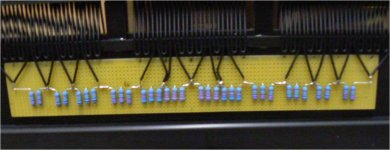
The number and wattage of resistors you need will all depend on the maximum stator voltage and the capacitance of the section the resistor is feeding. In my case, after calculating required voltage and power dissipation for the different segment resistors, I used three 1W resistors in series for the inner segments that produce the higher frequencies and two 1W resistors in series for the outer segments that only produce lower frequencies.See attachment for pic.
Playing pink noise at 30Vrms for 30 minutes the resistors get pleasantly warm, but not hot. When listening to music, even quite loudly, I have never had them feel even slightly warm.
Here is a link to a thread with some other posts on this topic.
http://www.diyaudio.com/forums/plan...-esl-project-file-translated.html#post2244336
Attachments
- Status
- This old topic is closed. If you want to reopen this topic, contact a moderator using the "Report Post" button.
- Home
- Loudspeakers
- Planars & Exotics
- DIY ESL: electric strenght of stator insulation?