Thanks for the info....looks like fun...
i think we all look at the Lucas esl panels ....i have the info here on the ESL sub from hell... spok to him on the phone onces... . ... tranfourmer winding books info not the book....The guy was a salesman....he was more in to the ....one born every min gurop..lot of adds in my old glassaudio books...MX
i think we all look at the Lucas esl panels ....i have the info here on the ESL sub from hell... spok to him on the phone onces... . ... tranfourmer winding books info not the book....The guy was a salesman....he was more in to the ....one born every min gurop..lot of adds in my old glassaudio books...MX
Actually 40% isn't all that bad as some have stated as this helps to dampen the diaphragm.
And a few seem to prefer it.
But any less than this may be an issue.
Lincane has a higher concentration of holes per area compared to that of your average perforated metal.
I have about 40% or so of open area using my window screen method by the time I get the coating thick enough and it sounds just fine.
The window screen gives me a very high concentration of holes per area and is very thin so this greatly reduce any Helmholtz effects associated by the dimensions of the holes.
I have been using Rust-oleum prodcts as well But I have found that ones with pigments may be conductive past a certain voltage.
Red oxide Primer is high in Talc and this is good and it is okay to use one coat of a pigmented type for a base color.
After that use a Clear acrylic for any additional coats.
I have measured as much as 1700v to 1900v or even as high as 2100v to 2200v or so per mil of thickness using this product.
There website claims about 1700v per mil for their conformal coating and it is the same stuff.
I use the 2X or 3X clears as it is more cost effective and goes on nicely and flows out well without much worries for running.
It does take a longer time for it too fully cure though.
However it does have a capillary action as all paints do so a thicker coat may be necessary due to the sharp edges.
A coat of primer greatly helps with this.
http://www.diyaudio.com/forums/plan...tric-coatings-fact-fiction-2.html#post2902754
As I have found out in my latest experiments and build.
http://www.diyaudio.com/forums/plan...tric-coatings-fact-fiction-2.html#post2893839
http://www.diyaudio.com/forums/plan...tric-coatings-fact-fiction-2.html#post2894427
I know these are all the same thread, but it deserves a good read through as well.
When you measure your Bias voltage make sure that it is a very high resistance probe as most are anyhow.
I have found in the past that if the resistance is too low the supply may not be able to supply enough current and give you a false reading as much as 20% lower or more.
The one I designed uses 30 X 10meg resistors and uses a opamp buffer to isolate the meters impedance.
It can be used without the buffer as well.
I individually measured each resistance and added a trimmer for precision adjustments but this is not necessary to just find out an average reading of the bias supply.
http://www.diyaudio.com/forums/plan...tor-insulation-mylar-coating.html#post2780153
Here is the schematic for referencing,
http://www.diyaudio.com/forums/plan...tor-insulation-mylar-coating.html#post2848194
I used this calculator for the resistor divider as it allows you to added your meter resistance in to the equation.
http://hyperphysics.phy-astr.gsu.edu/hbase/electric/voldiv.html


jer")
And a few seem to prefer it.
But any less than this may be an issue.
Lincane has a higher concentration of holes per area compared to that of your average perforated metal.
I have about 40% or so of open area using my window screen method by the time I get the coating thick enough and it sounds just fine.
The window screen gives me a very high concentration of holes per area and is very thin so this greatly reduce any Helmholtz effects associated by the dimensions of the holes.
I have been using Rust-oleum prodcts as well But I have found that ones with pigments may be conductive past a certain voltage.
Red oxide Primer is high in Talc and this is good and it is okay to use one coat of a pigmented type for a base color.
After that use a Clear acrylic for any additional coats.
I have measured as much as 1700v to 1900v or even as high as 2100v to 2200v or so per mil of thickness using this product.
There website claims about 1700v per mil for their conformal coating and it is the same stuff.
I use the 2X or 3X clears as it is more cost effective and goes on nicely and flows out well without much worries for running.
It does take a longer time for it too fully cure though.
However it does have a capillary action as all paints do so a thicker coat may be necessary due to the sharp edges.
A coat of primer greatly helps with this.
http://www.diyaudio.com/forums/plan...tric-coatings-fact-fiction-2.html#post2902754
As I have found out in my latest experiments and build.
http://www.diyaudio.com/forums/plan...tric-coatings-fact-fiction-2.html#post2893839
http://www.diyaudio.com/forums/plan...tric-coatings-fact-fiction-2.html#post2894427
I know these are all the same thread, but it deserves a good read through as well.
When you measure your Bias voltage make sure that it is a very high resistance probe as most are anyhow.
I have found in the past that if the resistance is too low the supply may not be able to supply enough current and give you a false reading as much as 20% lower or more.
The one I designed uses 30 X 10meg resistors and uses a opamp buffer to isolate the meters impedance.
It can be used without the buffer as well.
I individually measured each resistance and added a trimmer for precision adjustments but this is not necessary to just find out an average reading of the bias supply.
http://www.diyaudio.com/forums/plan...tor-insulation-mylar-coating.html#post2780153
Here is the schematic for referencing,
http://www.diyaudio.com/forums/plan...tor-insulation-mylar-coating.html#post2848194
I used this calculator for the resistor divider as it allows you to added your meter resistance in to the equation.
http://hyperphysics.phy-astr.gsu.edu/hbase/electric/voldiv.html
jer
Last edited:
The panels were marketed by Lucas as full-range.But, with his "interface" added in the circuit, there may be some bass cut-off. There is a switch that allows choosing "low" or "high" bass, and my panels are set on "high." Don't know what the cut-offs or slopes are: Lucas never revealed that info. I have to admit I am reluctant to play them really loud because I don't want to burn up them up, so I am always riding the volume.Maybe I should get over that?
I have a high-voltage probe and will take a reading as I am curious about variable bias being a problem.
The Lincane (gold-anodized aluminum) was sprayed with one coat of Rustoleum (hey, I'm still learning...) A thicker coating might be a good idea, but I don't have the capability to use automotive sprays or powder coats. Will have to investigate what I can do about that. Also, I think the perf pattern is too small. I remember reading somewhere that Lincane is 40% (ratio of holes to metal) and that isn't good from what I've read in this forum. I will definitely switch to other perf panels such as those used by Jazzman.
I expected a narrow sweet spot with these ESLs and tried to compensate by building four panels, which helped. Haven't tried rotating the panels vertically...might give that a shot.
Merry Christmas everyone!
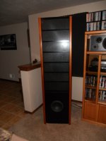
Your (4) 2'x3' panels provide over twice the surface area of my (2) 1'x4' panels-- and my panels can play pretty loud so I figure either 1) your panels use lower bias voltage or the diaphragm coatings are weak or 2) your concept of "loud" is louder than mine. Judging by the apparent thin coating on your stators and 1/16 d/s spacing, it seems to me you'd be getting a whole lot of arcing if those power supplies were putting out anywhere near the 10KV advertised.
Since flat panels are so directional and yours are relatively short and low to the ground, I wasn't surprised by your comment that you needed to sit on the floor in front of them to realize their full impact. Also, that transformer core size does not appear adequate for good bass output so you may be saturating the transformer before reaching the desired volume, especially if you are running all (4) panels with just those two small transformers.
One advantage to a tall panel is that it approximates a line-source at ear level to a normal seated listening position; whereas your shorter panels more approximate a beaming point source positioned below ear level, and the perceived volume drop with distance from a line source is only half that of a point source. Thus, even a smaller-area tall panel could actually sound louder than a larger panel positioned below optimal ear level.
Even so, ESL's may not be the best choice for really loud rock and roll, where volume may trump clarity.
How much stator open area is best is debatable for sure, but I should point out since you mentioned it that my panels shown on Jazzman's ESL Page (BTW, I am Jazzman) are actually now 40% open perf (although some of the photos show earlier panels which were 51% open). Going from 51% open to 40% open, I didn't notice much if any difference in output but I think the 40% open perf actually provides a bit of acoustic impedance which helps dampen diaphragm resonances. Some commercial speakers use a felt or cloth backing on the rear stator for that very purpose and some say lower open area (40%) is preferable for damping, and more metal equates to more charge area, which may also compensate for any volume drop resulting from lower open area. Just my thoughts on it...
I suspect you would perceive a LOT MORE SLAM if you were to stack the two panels vertically as you suggested, and I would also change to a bi-amp'd hybrid setup with conventional woofers providing the bass-- that would unload those transformers and let those panels really sing. If you decide to build new speakers using toroids, go with four of them per panel as Jer suggested. When I changed from EI-core trannies to the toroids driving my panels, the treble got a whole lot better.
Last edited:
How the Shockwave works....
I had an acquaintance at work (now several jobs and thousands of miles ago) that had purchased a set of shockwave plans. I read through them and what I could gather was that the panels were sequentially wired out of phase, the point being that the rear wave would be nulled out with only the front being propagated into the room. That, combined with the large number of panels was supposed to result in a high spl system. I think the "V" had the vertex positioned in the corner, although Mr. Lucas never responded to questions for clarification....
The sub-woofer ESL is made up of six panels of differing sizes stacked one behind the other. Two channels are arranged in a V configuration. I believe the panels are wired in parallel, but the sub itself is supposed to be wired in series with other mid/high range speakers (whether ESL or conventional speakers, I don't know.) I haven't built these subs so I can't pontificate on sound issues. I have the plans for the subs, flat panels, and curved panels if anybody wants them.
I had a good experience buying stuff from Lucas over a year or so, and his "sales manager" Tim Kelly seemed OK. Sorry to hear some have been ripped off. I guess it was hard to produce/market ESL kits in the old days even when Speaker Builder was around...even harder now, I suppose. He didn't lack for marketing hype....
I had an acquaintance at work (now several jobs and thousands of miles ago) that had purchased a set of shockwave plans. I read through them and what I could gather was that the panels were sequentially wired out of phase, the point being that the rear wave would be nulled out with only the front being propagated into the room. That, combined with the large number of panels was supposed to result in a high spl system. I think the "V" had the vertex positioned in the corner, although Mr. Lucas never responded to questions for clarification....
David Lucas ESL experience
Waldtraut, Charlie,
Have played with DIY ESLs over the years: also got some stuff from David Lucas back in mid 90s, and built some with 2'X3' curved lincane panels to create a pair of 2X6 panels, and ran full range with rolled off low end. Used HV power supply tranny from bug zapper, and still have parts. I used the 77 series Lucas transformers, which had to be plate transformers for tubes, but never was able to cross reference to OEM. I got curious and tore apart one of the potted EQ units, which is, in fact, a potted Radio Shack 273-151B transformer, 120V, 60 Hz in and 12.6V-0-12.6V center tapped secondary (2 black wires on one side of Luca box are the 120V primaries, and 2 yellow/1 black wires on other side are the center tapped secondaries, with CT black), so it was a EQ choke of sorts, any one chime in at what Lucas was doing, but I assume it was to counteract the normal 3db/octave rise inherent in an esl panel. Sound was typical for a curved esl, delicate, non-fatiguing for hours on end, but of course, no bottom end and a very large and diffuse sound, even standing up some 6.5' off floor. Diaphragm was Sanders 1/4 mil polyester film, and spacers were standard 1/16" thick foam spacers, and way too much tension in transverse direction necessitating a number of well placed 1/16" OD plastic tubes pressed into center of aft side stator holes due to saddling (did not understand inherent saddling that occurs on diaphragm when any degree of tensioning occurs in transverse direction on curved ESLs (I don't think Mike Kelly/David Lucas understood this at the time either). I am sure Calvin understands this well. Not playing much with ESLs much these days, but understand much better how ML make theirs, and may get back into it some day. I am in Charleston, SC, so may hook up with Charlie some day to compare notes on flat and curved concepts.
.... I am in Charleston, SC, so may hook up with Charlie some day to compare notes on flat and curved concepts.
If you're ever in Savannah, I would love to have you drop by an bring your favorite tunes. And if I'm ever in Charleston....
(PM'd you my address & phone)
I'm2Sure2:
Congratulations on cracking the mystery of the Lucas "Interface," the potted "old work electrical" blue box that he sold claiming it "equalized" the response of his ESLs. I've always wanted to put it in an oven and melt the potting compound to see exactly what he did, but frankly the interfaces worked pretty well with the Lucas designed ESLs, so I left them alone and continue to use them with the Jazzman (copyright Charlie Mimbs) ESLs that I built.The interface allows the user to select either of two outputs, one which increases the bass response, the other decreases it. I still use the Lucas EI transformers but expect to replace them with toroids recommended by Charlie very soon. I used the Lucas flat panel ESLs and they worked without a problem for 16 years (although they never sounded so good until i stopped using them full-range and rolled them off at 330 hz. with an electronic crossover per Charlie.) Thanks for your input!
Congratulations on cracking the mystery of the Lucas "Interface," the potted "old work electrical" blue box that he sold claiming it "equalized" the response of his ESLs. I've always wanted to put it in an oven and melt the potting compound to see exactly what he did, but frankly the interfaces worked pretty well with the Lucas designed ESLs, so I left them alone and continue to use them with the Jazzman (copyright Charlie Mimbs) ESLs that I built.The interface allows the user to select either of two outputs, one which increases the bass response, the other decreases it. I still use the Lucas EI transformers but expect to replace them with toroids recommended by Charlie very soon. I used the Lucas flat panel ESLs and they worked without a problem for 16 years (although they never sounded so good until i stopped using them full-range and rolled them off at 330 hz. with an electronic crossover per Charlie.) Thanks for your input!
I got curious and tore apart one of the potted EQ units, which is, in fact, a potted Radio Shack 273-151B transformer, 120V, 60 Hz in and 12.6V-0-12.6V center tapped secondary (2 black wires on one side of Luca box are the 120V primaries, and 2 yellow/1 black wires on other side are the center tapped secondaries, with CT black), so it was a EQ choke of sorts, any one chime in at what Lucas was doing, but I assume it was to counteract the normal 3db/octave rise inherent in an esl panel.
Can you post a schematic, or describe how the wires from the RS 273-151B transformer were connected to the step-up transformer(and any other crossover parts)? That might give us a clue as to what Lucas was trying to achieve.
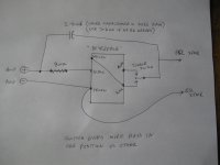
Here is a schematic I drew up of the Lucas "Interface." Lucas claimed this circuit allowed the amp to see an 8 ohm load constantly, and by adjusting the capacitor value you could "adjust the EQ for more or less bass." The toggle switch also allowed for "more or less bass," but you had to determine which setting was "better" by listening. Lucas wasn't specific. Hope this helps, and any info re: how/if the circuit works would be most informative.
Attachments
Wow.............thanks for the pic........an info on this.........i well try this on my Acoustat 121 interfaces an we well see...............Mr Pass told me years ago ......a transfourmer is a Transfourmer...is a tra....you get it.......an that i should use one ...in one of his Class a Diy Amps....insted of the res. that i keep smokin......Trany.worket great........... an never even go hot
thanks for all an any info on ESL........setups.
Long live Acoustats......
thanks for all an any info on ESL........setups.
Long live Acoustats......
Last edited:
Here is a schematic I drew up of the Lucas "Interface." ...Hope this helps, and any info re: how/if the circuit works would be most informative.
The schematic is most informative and is what I had suspected....one Lucas "mystery" solved
It is the patented Audiostatic Mirror drive circuit which provides a +6dB or more bass boost for equalizing the dipole roll-off of full rang dipole ESLs.
Audiostatic used a large AT(autotransformer) with a center tap, Lucas is using the center-tapped 12volt secondary for the same purpose but with less power handling capability. With the switch in the down position the boost would be +6dB. The results with the switch in the up position would depend on the phasing of windings...either more or less boost.
Basically it works by sending high frequencies directly to the step up transformer thru the coupling capacitor connected to the top of the AT winding, but sends low frequencies to the center tap of the AT which then doubles the voltage at the top of the winding. This creates a shelving network with LF boost of +6dB.
For further details, see the attached Peters US patent.
Attachments
Last edited:
ESL power supply
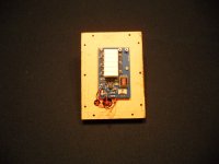
I built a set of ESLs with the kit I purchased from David Lucas in the late 90's. Threw most of it away and built them using my own parts as most of it was junk, especially the power supply design. I think I ended up using a 555 and LM386 driving a low voltage transformer then multiplier. Worked OK for awhile, but when one of the panels failed, I started over from scratch. Came up with an interesting design based on a low cost CCFL xfmr that is self excited. CADed the boards in the attached photo and they have been working great ever since. Runs from a 9V wall wart and produces about 3KV.
Also found some great double sided tape to use for spacers: 3M VHB in .063" thickness. They use it to replace screws it bonds so strong. Went with steel stators instead of alum, much stiffer and less prone to damage.
Attachments
David Lucas Equalizer
Waldtraut,
Just confirming that the Lucas EQ unit that I discovered was a Radio Shack 25.2 volt center-tapped power transformer, is wired as the group has surmised: the yellow/black/yellow wires on one side of the unit are the transformer's center tapped secondary, and the two black wires coming out of the unit are the 120V primary wires. The xfmr was potted by inserting it into blue electrical box and filling with white sand, then potting with about 1/2" of white potting compound on top of that, so digging one out is no problem at all.
I should mention that the Lucas $99 EI step up transformer has the ID number "RE 90823" printed on the case, the dimensions are: 2.7" wide, 3.2 " high, and 3.3" deep, and the laminated core looks to be about: 2.6" wide, 3.1" high, and 1.5" deep. Wires on one side are: Orange/brown/red, and wires on other side are:white/blue/tan(yellow?),purple/green. The green, white, and purple wires were not used by Lucas. I have tried searching for this tranny in all the major US transformer catalogs, but no luck with that number and dimensions (if anybody is interested, or just curious). BTW, the overall dimensions include the can covers on both sides. It is painted black, and might weigh a couple of pounds at the most.
I still have my 2x3 curved lincane panels, but have not used them for some years, and my wife wants me to get rid of them. In my opinion, aluminum lincane at .020" thickness, is not very strong for ESL use, unless it were backed with some form of reinforcing grid. Curving them helped with rigidity, but they were still not that rigid.
Just another of my 2 cents if Lucas info (my contact there was a guy named Tim, FWIW, so I am not even sure if a David Lucas ever existed in the company.
THanks Waldtraut............Bolerst.....an others.......
David Lucas ........who was this guy?
well i gess we may never know..............but there was a lot of Adds in a lot of Audio Mags...for sure......... frount an back covers,.full pages..............i was in the Audio bizz at the time an called...got the info sent to me,far as i went....oh well
David Lucas ........who was this guy?
well i gess we may never know..............but there was a lot of Adds in a lot of Audio Mags...for sure......... frount an back covers,.full pages..............i was in the Audio bizz at the time an called...got the info sent to me,far as i went....oh well
Last edited:
- Status
- This old topic is closed. If you want to reopen this topic, contact a moderator using the "Report Post" button.
- Home
- Loudspeakers
- Planars & Exotics
- David Lucas ESL