Thank you for the complement!
Yes this is for biasing my ESL's and for testing of materials so it is a very stiff supply.
Upon prior testing I had found it to sag a bit on some heavy peaks and and did see some audio modulating it as well.
But this didn't seem to cause any major issues in sound quality.
But it is for that reason I will be incorporating a feedback regulated system as the changes I saw were as much 200v maybe a little more.
This supply with its High range of voltage and ample amount of current allowed the panels to stay fully charged at all times and they played with quite some authority.
Much more so than running at the normal 2Kv or so of bias.
I truly got every ounce of efficiency out of the panels.
I normally just use a 10 megohm resistor to feed the panels with but in one case were I had three panels hooked up I had to use 3 resistors for 30megohms to feed the panels.
I had witness a strange thing of the balance between the panels would change as a raised or lowered the bias voltage.
Just like moving the balance control on your receiver.
I am not sure of the exact cause of this yet but raising the feed resistors stopped it.
I also had experimented with putting resistors on both legs of the power supply.
This may be beneficial as well, as it seemed to cut down the modulation level of the initial modulating of the bias voltage.
And it should be a must do if you plan on using one bias supply to feed the panels in stereo.
As there will be some degradation of crosstalk between the two channels with out them.
I haven't had the chance to elaborate on this as I was running the panels mostly mono in order to examine the nuances of the individual panels and configurations of trying absorb the back wave or to increase its path for more bass.
My panels are small at a 3.25" X 9.75" Diagphram size, But I do have some 8" X 22" panels as well but they need new frames.
My little panels have a better stator coating and have been tested to 7.5kv with no leakages,this is why I haven't done any tests with the bigger panels yet.
jer")
Yes this is for biasing my ESL's and for testing of materials so it is a very stiff supply.
Upon prior testing I had found it to sag a bit on some heavy peaks and and did see some audio modulating it as well.
But this didn't seem to cause any major issues in sound quality.
But it is for that reason I will be incorporating a feedback regulated system as the changes I saw were as much 200v maybe a little more.
This supply with its High range of voltage and ample amount of current allowed the panels to stay fully charged at all times and they played with quite some authority.
Much more so than running at the normal 2Kv or so of bias.
I truly got every ounce of efficiency out of the panels.
I normally just use a 10 megohm resistor to feed the panels with but in one case were I had three panels hooked up I had to use 3 resistors for 30megohms to feed the panels.
I had witness a strange thing of the balance between the panels would change as a raised or lowered the bias voltage.
Just like moving the balance control on your receiver.
I am not sure of the exact cause of this yet but raising the feed resistors stopped it.
I also had experimented with putting resistors on both legs of the power supply.
This may be beneficial as well, as it seemed to cut down the modulation level of the initial modulating of the bias voltage.
And it should be a must do if you plan on using one bias supply to feed the panels in stereo.
As there will be some degradation of crosstalk between the two channels with out them.
I haven't had the chance to elaborate on this as I was running the panels mostly mono in order to examine the nuances of the individual panels and configurations of trying absorb the back wave or to increase its path for more bass.
My panels are small at a 3.25" X 9.75" Diagphram size, But I do have some 8" X 22" panels as well but they need new frames.
My little panels have a better stator coating and have been tested to 7.5kv with no leakages,this is why I haven't done any tests with the bigger panels yet.
jer
Last edited:
I like this statment....
This supply with its High range of voltage and ample amount of current allowed the panels to stay fully charged at all times and they played with quite some authority.
Much more so than running at the normal 2Kv or so of bias.
I truly got every ounce of efficiency out of the panels.
This is my deal i have panels here from 9"x40" to16x48.that work on 250hz up an then the 9"48" fullrang......This bias deal is the way to get all you can out of the panels
I have a tube amp here that puts out 50w-60ws.....an with the bias right....up in the 3k an up on all the panes....i can give all the SPL you need on any input...that why i am doing this other need to get a headsup...on the esl bias.... it was for years nothing that i even look at...it was caps an coils crossover an wire an amps an preamps..LP...CD...DVDs....the bias makes more of a diff with esls than all put to gather......lot of fun for DIy people
Thanks for your time
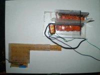
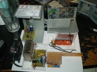
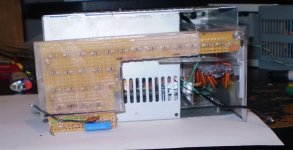
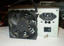
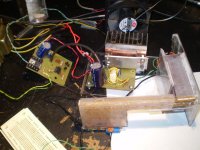
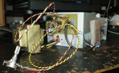
Here are some pictures of what I have done so far.
It reminds me of a high tech Tetris puzzle as every piece was custom made.
Had I already knew exactly what parts were needed in the first place I probably could have made it fit completely inside the box that I am using.
I do have some bigger ATX style power supply boxes but I think that they still work.
The only thing that is missing from the pictures is the 25.2 Volt C.T. 2 amp transformer and the voltage control knob as well as the voltage control daughter board that has yet to be created.
And a few mounting brackets then I will build a plywood box around it for protection.
All of the components shown are the working pieces as it was built and just needs to be wired up.
Enjoy !!
jer
Attachments
Last edited:
Vary cool
I have had a lot of ESL but the only one with a voltage control on the bias Was SoundLab A1.....you could set the bias for the best out put everday if you liket...
so i put this in my bias set up....what a big diff this makes...ever if you just put a pot on the 120ac coming in from the wall....now for me i well say the soundlabs can sound ok...but....you have to drive them with sand amps ...like a dead short move on from SL...wont be going back...The Frist ESL i got were the AcoustatXs....now were talking BIAS the power transfourmer put out 5kv.......i could set in the dark an see the wires in the panel liteup to the beet of the sound,freky....man thay sounded good but the THD was so low that i always over drove them....i have been looking for a 3k-4kv tranfourmer to use in the bias...i think it would sound better than all the diods.
Thanks for the pix
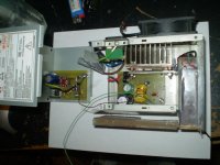
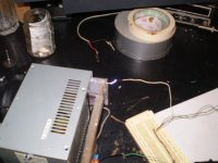
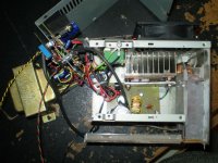
I just finished the supply accept for mounting it in a wood box and it is operational at least.
The picture shows the voltage to be 10.4 kv but it is actually running at a consistent and stable 12.8Kv.
The error is caused from the loading of the scope or probe or something as my probe broke although it is still functional.
When the probe is in 10X mode both the scope and the meter read the same at 12.8kv and when the probe is in 1X mode both read a maximum of 10.5kv.
I get a 60 cycle hum level typically 5V at a full 12.8kv output with a maximum of 10v has been observed.
The 160khz supply ripple is less than this at the measuring point as there is a small .01uf filter cap on the output of the divider.
Later after I get it mounted better and start working on the feedback regulation I will test it again without this cap.
Now that every thing is mounted and properly grounded and in a metal box there hardly any noise and is quite low for any at all.
I get a nice solid line and I can see the voltage drop as the air starts to conduct as I slowly close the gap until conduction as well as seeing the voltage change is the length of the arc is adjusted.
WoW!!!
This thing works perfectly and is quite stout and very stable as is.
jer
P.S Yes,Tyu, I pushed my panels until they glowed as well and there wasn't much noticable distortions except when the amp was clipping.I was running them so hard they where almost a plasma speaker. he,he,he
Attachments
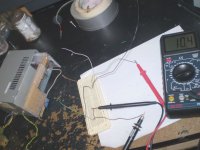
I did some checking an the measurement error issue.
The input impedence of my scope is 1 megohm and my meter has an input impedence of 10megohm as well as the 10X setting on my probe maybe more at 20megohms as I can't seem to locate the data on the probe right now.
This corresponds to the errors according to this online calculator,
Voltage Divider
So the buffered output is going to be imperative for a very accurate reading of output voltages.
So I will get on this soon,But the cool thing is that it is now operational and I can now get back to some ESL testing and great listening besides.
Jer
It has been a long time coming, from this,
http://www.diyaudio.com/forums/plan...t-panel-angles-8-vs-9-panels.html#post2170344
jer
http://www.diyaudio.com/forums/plan...t-panel-angles-8-vs-9-panels.html#post2170344
jer
I just got the bias supply feedback circuit working !
Super simple with one dual opamp.
I it is now rock steady regardless of the load, until of course a large current is drawn do to an arc and then it recovers very quickly.
With the buffered output for the metering there is no more error from loading on the divider stage.
although It needs to be recalibrated chances are it is producing a full 14Kv ( 13.87Kv ) regulated output maximum.
It does a 0V to 13kv regulated output that is proportional to the input control voltage of 1v per 1Kv.
I may eventually go as far as making a digital control unit for it as the hard part is now done and will follow a 0 to 13v input with a proportional 1000 times voltage output.
I am so excited now I think I am just repeating my self.
One more little board to create and it will be useable and voltages will now be able to be set accurately and stay stable.
Good enough for some High resistance measurements of materials as well,one of the soul purposes of this project.
Merry Christmas and Happy Holidays to all !!!

jer
P.S. It has been holding a rock steady 13kv while it took me over 30 minutes to finish this post,Buy monitoring the bufferd output with my scope! he,he,he
Super simple with one dual opamp.
I it is now rock steady regardless of the load, until of course a large current is drawn do to an arc and then it recovers very quickly.
With the buffered output for the metering there is no more error from loading on the divider stage.
although It needs to be recalibrated chances are it is producing a full 14Kv ( 13.87Kv ) regulated output maximum.
It does a 0V to 13kv regulated output that is proportional to the input control voltage of 1v per 1Kv.
I may eventually go as far as making a digital control unit for it as the hard part is now done and will follow a 0 to 13v input with a proportional 1000 times voltage output.
I am so excited now I think I am just repeating my self.
One more little board to create and it will be useable and voltages will now be able to be set accurately and stay stable.
Good enough for some High resistance measurements of materials as well,one of the soul purposes of this project.
Merry Christmas and Happy Holidays to all !!!
jer
P.S. It has been holding a rock steady 13kv while it took me over 30 minutes to finish this post,Buy monitoring the bufferd output with my scope! he,he,he
Last edited:
I just finished the bias feedback regulator as I had last post,But I had found out that it wasn't tracking properly or linearly.
But it is now!!
I had set it for -10.11kv in a stability test and after about a 15 minute warm up time it settled down to -10.07kv and held that for 6 hours straight without one bobble or any deviation what so ever.
Even after pulling a few arcs off of it,It instantly settled back to -10.07Kv.
I can even set it to a -10volts out or anywhere sub 100v if I wish.
I can't wait to get some more resistors together in order to do a load test.
It will do a full -14Kv on power up but after the warm up period this drops to about -13.85Kv.
It idles nice and very quietly at -10Kv and then the regulation ramps up kicking the fan up as well when pulling some current or arcs ,But the voltage never goes above the set value.
I just happened to have a 78L007 (7v) to use as a refference voltage so it now tracks at .5V per 1000Vout.
Later on in My list of thing to add will be a digital control and display.
The regulation is superb and the ripple is on the order of .3% or better for a full 13kv out.
This thing turned out much much better than I had anticipated it too be.
This supply can also be modulated but I haven't gotten very good results yet as there are to many filter caps along the way.
I will save that idea for the next one that I build.
I am now working on the control PCB so I will have it finished with in a few days.
And I can't wait to start putting it to some good use.
Once it is back running with the control board, I will post a new up to date schematic as promised.
Happy New Years, DIYer's !!!!!
jer
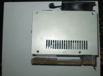
Hello DIYer's.
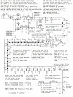
Here are a couple more final pictures of the ESL VARIABLE BIAS SUPPLY.
As well as the schematics and final notes as tested on January 4, 2012.
The non linearity problems have been fixed and is only slightly off at its extreme high and low ranges at above 13.3kv and about below 1kv as this is very acceptable.
Between these voltages it is completely linear and very stable with no deviations at all.
Not one Bobble on the meter what so ever.
The accuracy is better than 10v on the H.V. side as my meter only goes to .01v resolution.
Even after a very long running time at 10Kv as stated earlier.
If one should like to make this supply I have the prints available for the PC Boards as well upon request.
Enjoy !!!
jer
P.S. The Black and yellow twisted cable is the meter out line.
A few more features I may add at a later time is,
1# A digital control unit
2# A deviation metering circuit to monitor the drag on the supply during coating breakdown test.
3# a load resistor circuit that shows current draw or some thing similar to 2#.
Attachments
Last edited:
One of the IRF510 FET's gave out today.
I'm not sure why as the thing has been working perfectly and was used for many stator coating stress tests and arc tests with no problems at all.
I did go through many of them while devolping the power supply.
This sets me back abit,So now the search is on for some better FET's or maybe a revamp of the drive system.
Everything else is working fine and I will pop in a new one to verify this.
The IRF510 is a weaker type of FET and is fun to work with but it is not worth the money that Radio Shack charges for it although I did make it work in this circuit.
I will post my results after I replace it and start working on a better output circuit and/or FET replacement.
Oh, The Fun of R&D !!!
Cheers!
jer
I got the power supply back running today.
It took just one FET to do it.
I couldn't find any thing out of the norm to cause the failure.
I thought that maybe the drive got to high on the gates but they weren't,so I just replace the bad FET.
While I had it apart I did try a IRFZ42 in place of the the bad FET using the installed 1K resistors as a load with the output transformer disconnected and it worked as well.
Although it did show a slightly lower gain but a nicer output waveform than the IRF510 in which was expected due to the much lower on resistance (RDSon).
A slight tuning of the gate drive transformers primary will probably be all that is needed to make it perform properly.
I wasn't in the mood to re-tune it at this time.
Should another one fail I will look more deeply into the situation.
So, Let the Testing Resume !!!!
Cheers!
jer
I had thought about that,alexburg,
But is that really possible being that the output stage is configured as a classic class B pushpull linear amplifier?
I am suspecting that some high voltage may have crept in from the ground side off of the stepup transformer driving the ESL panel because I forgot to use some isolation resistors to the panel when I hooked it up.
Also it is possible that a charge could have built on the surface of the plastic panel used to mount the amplifier board and on the panels high voltage section is encased in.
I was thinking that I may need to add some static shields.
Some times the thing seems be to energizes even on the ground side as can feel when I touch the voltage adjust or the ground case as the high voltage gets into everything above about 10Kv or so.
I found this to be true as well when I was working on the feedback circuit and was very surprised that the opamps could survive in this condition as the whole thing was energized with a small high tension.
All of that went away for the most part once I had it properly mounted in its case.
It is not doing this now and the case and Voltage control now seems to be cold
.
It may very well have been a bad solder connection on one of the three ground wires coming off of the High voltage section.
Everything is star grounded to the main amplifier board including the case and earth ground.
The control boards power is are daisy chained from the star point on the main amplifier board and are common grounded to the case through the mounting screws as well so they are well protected too.
I can sit here and draw arcs off of it all day with no issues.
But when I hooked up the ESL (that was insulated from the top of my desk with a pane of glass) it would reset my computer every time it arced in the panel.
Now I know I shouldn't have its power source common to my sensitive electronics but nothing was affected until I hooked up a panel for some breakdown testing!
Hmmmmmm...........
jer
Last edited:
Here is a source of high voltage power supplies and stuff as well as some ready made transformers and core pieces that might work in the power supply that I had designed or could be used to create some thing similar.
Also some little supplies that may be used for ESL bias supplies.
Very cool stuff!
Some expensive and some very reasonable prices,
High Voltage Transformers
Enjoy !!
jer
Also some little supplies that may be used for ESL bias supplies.
Very cool stuff!
Some expensive and some very reasonable prices,
High Voltage Transformers
Enjoy !!
jer
Last edited:


WoW!!!!!!
I just discovered that it has been three years today that I have finished and finalized this supply back in post #50 !!!
It still works Great today, and, I have not had one issue since then with it, or its accuracy!!
Except for the issue of the Blown FET once Two years ago, better FET's solved that!!
Cheers!!!
jer
Last edited:
Hello DIYer's.
Here are a couple more final pictures of the ESL VARIABLE BIAS SUPPLY.
As well as the schematics and final notes as tested on January 4, 2012.
The non linearity problems have been fixed and is only slightly off at its extreme high and low ranges at above 13.3kv and about below 1kv as this is very acceptable.
Between these voltages it is completely linear and very stable with no deviations at all.
Not one Bobble on the meter what so ever.
The accuracy is better than 10v on the H.V. side as my meter only goes to .01v resolution.
Even after a very long running time at 10Kv as stated earlier.
If one should like to make this supply I have the prints available for the PC Boards as well upon request.
Enjoy !!!
jer
P.S. The Black and yellow twisted cable is the meter out line.
A few more features I may add at a later time is,
1# A digital control unit
2# A deviation metering circuit to monitor the drag on the supply during coating breakdown test.
3# a load resistor circuit that shows current draw or some thing similar to 2#.
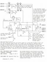
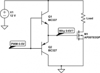
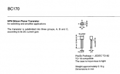
It had been pointed out to me that the BJT's in this schematic are swapped, but it is the proper connections as it is shown on my board, like it is in the First image.
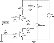
However....... It also can be configured as it is shown in the Second image !!

Well with my dyslexia it got rather confusing for me even when I had designed the circuit !!!
Reading the pinout's in the datasheets is also confusing and took me sometime to figure out how I screwed this up.
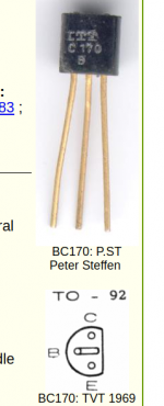
When I read datasheets the Top view shown in the third picture is how it should shown..................... With the pins as circles !!
And the Bottom views are supposed to be shown with the pins as solid dots.
The datasheet's that I used showed the top view of the package with the pin as solid dots like in the Fourth image.
Being an Orthagonal drawing I guess I should have known better.
That is how this schematic got screwed up.

So the connections in the schematic ARE CORRECT only the NPN should be on Top ........
And the PNP is supposed to be on the bottom.
This power supply is still working Excellently after 5 1/2 years of service.
I HATE posting misinformation !!!
It is something that I just do not do, if I can help it !!

But I Guess I Goofed !!

Sorry about that !!! !

Cheers !!!!

jer
Attachments
Last edited:
- Status
- This old topic is closed. If you want to reopen this topic, contact a moderator using the "Report Post" button.
- Home
- Loudspeakers
- Planars & Exotics
- how can test the stator insulation and mylar coating?