Alex,You are absolutely correct and I do apologize for coming off a little on the offensive side.
However let me set the record straight for the third time that all was doing is to present the topology that I used to create my bias supply.
And that the schematic depicts the parts that I used as is.
I never stated that these are the parts that should be used as a final product.
And I did state that this was just a rough draft and there is much room for improvement.
I my self, the designer of the circuit, was quite amazed that the thing even worked with those particular diodes at all.
But it did, and it gets me by for now and thru the last year it has been working flawlessly.
I am sure that by replacing the diodes with the proper ones it should sustain a continuous arc at 1cm gap instead of the 4mm gap that it does do.
I do experience this drop in output voltage even when a 100 gigohm resistor divider is connect to the output to measure the voltage as observed on the scope.
I'm sure this is because of the poor recovery time of the diodes.
The easiest way to combat this is to rewind the output transformer core to operate at a much lower frequency and that will allow me to use the multiplier stage that I have already built and invested in.
As well as solving the problem of the 555 timer being barely operable at the extreme end of its frequency range.
Also being that I am experimenting with cores ripped out of old supply's they vary in sizes and material types, I don't yet have a recipe of using (Z)core and (X) amount of turns to be consistently repeated by the average DIYer.
This is why I have never post the schematic in the past and I probaly should not have done so with the circuit values displayed.
The data sheets that I have found list the recovery times as 2us for the 1N4007 and 1N5399 that I am currently using and there was one that I had found that listed it as .8us which is what inspired me to try them.
But I can't seem to locate that file now.
Although it is not an efficient way to go by any means ,It did work in a pinch.
I do have quite a few of the proper diodes but not enough to accomplish my goals at this moment.
Otherwise I would have used them and displayed their part number in the shcematic.
If one were to come out and say "I would like to use that circuit" ,Trust me I would be the first one to come out and say that those diodes are not the ones you should use and that you should use diode XXXXX for that circuit.
With Best Regards. jer
Attachments
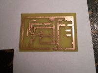
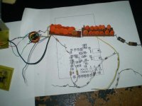
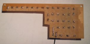
I got a Samsung ML-1865w laser printer for $50 a couple of weeks ago and it works great for making PCBoards.
So first on my list (of course) is my variable bias supply.
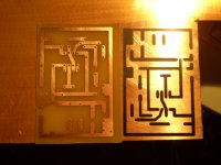
I have drawn up two versions so far of the driver circuit, one with the class B output stage and one without.
I have decided to just make the 555 driver circuit so far as not to waste PCB material for now,So that I can work on lowering the frequency and work on the recipe for the transformers so that everyone can reference it.
As well as using the 1N4007 diodes more efficiently due to a lower frequency.
As it is right now the timer is set at 163khz at 50% duty cycle.
By the time I get to the final version it will have a voltage feedback circuit for too aid in regulation.
Although it has been proven very stable without it.
As well as a buffered output voltage for direct voltage measurement of the output bias voltage with a DVM or VOM at 1000v per 1v.
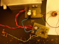
So here is what I have done today.
Enjoy,Jer.")
So first on my list (of course) is my variable bias supply.
I have drawn up two versions so far of the driver circuit, one with the class B output stage and one without.
I have decided to just make the 555 driver circuit so far as not to waste PCB material for now,So that I can work on lowering the frequency and work on the recipe for the transformers so that everyone can reference it.
As well as using the 1N4007 diodes more efficiently due to a lower frequency.
As it is right now the timer is set at 163khz at 50% duty cycle.
By the time I get to the final version it will have a voltage feedback circuit for too aid in regulation.
Although it has been proven very stable without it.
As well as a buffered output voltage for direct voltage measurement of the output bias voltage with a DVM or VOM at 1000v per 1v.
So here is what I have done today.
Enjoy,Jer.
Attachments
I found an interesting page about Diode recovery times and of a tested 1N4007 as per the last time we were discussing this.
It is a great read and gives alot of insight as to why the 1N4007 happened to work in my circuit.
But as stated before the UF4007 would be better suited and cost about the same.
Diode Turn-On Time
jer
P.S. Also I found this cool spreadsheet for calculating a voltage multiplier stage as mine uses 22 stages and this spread sheet is pretty right on with measurements I got out of mine.
http://www.voltagemultipliers.com/other/Multiplier Design.xls
Last edited:
I got a Samsung ML-1865w laser printer for $50 a couple of weeks ago and it works great for making PCBoards.
So first on my list (of course) is my variable bias supply.
I have drawn up two versions so far of the driver circuit, one with the class B output stage and one without.
I have decided to just make the 555 driver circuit so far as not to waste PCB material for now,So that I can work on lowering the frequency and work on the recipe for the transformers so that everyone can reference it.
As well as using the 1N4007 diodes more efficiently due to a lower frequency.
As it is right now the timer is set at 163khz at 50% duty cycle.
By the time I get to the final version it will have a voltage feedback circuit for too aid in regulation.
Although it has been proven very stable without it.
As well as a buffered output voltage for direct voltage measurement of the output bias voltage with a DVM or VOM at 1v per 1000v.
So here is what I have done today.
Enjoy,Jer.
I mean't 1v per 1000v out .he,he
jer
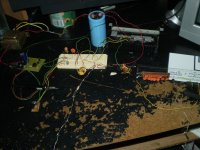
I got my power supply back running again last night (after over a year).
With two simple mods I got it working better than the last configuration.
One was swapping the driver core to one of a higher permeability and the other was to change the 555 timer resistor connection to one resistor so that it is a 50% duty cycle although I am not sure if this is helped at all yet.
I have also been able to directly drive it from my signal generator as well.
From it, It makes no difference as to if the wave is a sine wave or a sqaure wave, either works well,but I prefer the sine wave drive better.
I will use a sine wave drive when I build the second one as I am still not getting a symmeterical output waveform using the 555 driver circuit.
Never-the-less it works fine for its intent and packs quite a wallop of a continuous arc of at least 1/4" to 3/8" and will jump nearly 1/2' when the charge is built up on the capacitors.
This is with a 14 stage multiplier and does better than when I had 24 stages hooked up when I first built it.
This is amazing for some capacitors rated at 500v from Radio Shack.
Once I get a voltage divider made and find out exactly what voltages are I may add more stages because 500v capacitors are all I have for now.
But so far no failures as of yet even with the major increase amperage performance and voltages pulling continuous arcs from it.
I have tried every different kind of core I have and I have found that most only work at about 80khz and above this is typical for powdered iron cores.
I was trying to get down to the 30khz to 40khz range but this requires far to many primary turns to make the smaller cores work properly or even at all in some cases.
I have found that the line input filters seem to work the best with little to no modification except for adding one simple winding for the gate drive and the output transformers.
I still haven't had any major issues with the diodes as regards to the reverse recovery time with my clock rates of 160khz so modifying the transformers is not an issue at this point in time.
It requires far to many turns and time to do so.
After a little research CoilCraft may have a pair of off the shelf transformers that would work that can be had for less than $5.
But if one were to try this I would go with some fast recovery diodes for good measure.
The class B amplifier stage is simple and requires two FET's and A Resistor.
It's bandwidth is from about 50khz to 300khz but it's useable performance is from about 90khz to 250khz when loaded with the multiplier stage in which this brings me to 150khz to 170khz for peak performance.
I'm getting in excess of 600v P-P to feed the multiplier stage as my scope can only display 400v P-P I will have an exact figure next time after I build the voltage dividers for measuring the high voltages.
At which time I will also try to do some power measurements as well.
I will post some more pictures after I get the rest of the thing on some PCB material and off of the breadboards as well as pictures of it in operation.
All I have left to do is the Class B power amp stage for now.
jer
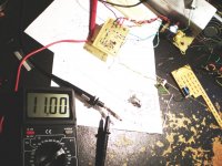
I just made a 1000:1 voltage divider of 138.65 megohm resistor string and 140k ohms.
It should be accurate within A few percent or at least 1% or better.
I Did my best to verify it with my scope and a Brand new DMM which seems to be fairly good.
Although, It is not with in specs in some of its ranges but still within 2% to 3% it is a Cen-Tech P37772 that I picked up for $19.99 on sale at Harbor Freight.
I may take it back and try for a another as it is still not a bad deal as measures capacitance as well and accurate to 1pf.
So far I have measured 4.67Kv from the supply with only about 100v of ripple.
It only pulls .4 amps when it is set at full power with no arcing from a supply of 18v.
Start some arcing and the Supply current goes as high as 3 amps and pulls 4.5 amps with the multiplier stage shorted as it is about the limit for my transformer.
It chugs along quite nicely at 1 amp with some mild arcing.
So, it does use much power at all.
With a constant steady arc it still maintains about 2kv to 3kv even with the resistor string attached.
The maximum arc length is about .28" and is the longest it can do with this configuration.
This is plenty to power my ESL's but my goal is 10kv so I will have to add the extra multiplier stages that I already have made.
I will have more on this later.
jer
I was able to get more voltage out of the supply by increasing the maximum drive voltage from 10v to 13.14v.
This test was done at this level.
However increasing the drive that much causes the Fet's to run rather warm.
I did not measure the current draw from the main supply and I am sure that it was quite high from the heat that the FET's produced.
Especially for not pulling any constant arcs, But, There were no failures.
These are IRF510's and using a FET with a lower Rds such as an IRFZ42 or similar this may not be an issue.
Using the lower drive voltage the IRF510's hardly get warm at all ,and ,will require a very minimal heatsink area.
Even though I was able to get close to an extra 1KV out of it doesn't justify the higher voltage drive as two more stages of the multiplier can do this without causing excessive current and heating of the FET's.
Due to the heating of the FET's it seemed to also cut down on the available current required to maintain a constant arc as well.
Even though maintaining a constant arc is not the goal it is a good test of performance and durability nevertheless.
I also made I slight change of the FET's bias configuration and I had a slight improvement with that and I will post a revised schematic when it is finished and off of the breadboard.
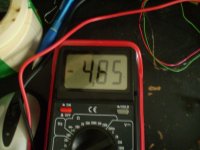
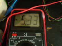
The one reading of 4.85v from the meter was thru a 1megohm resistor off of the divider and seemed to coincided with the reading of the scope waveform with the 10x setting on the probe and not going thru the 1megohm resistor.......hmmmm.
This is were I question the accuracy of the meter a little,But this discrepency is with the readings on a couple of ranges not being exactly the same with just the decimal point changing place.
But after a few more tests showed that my voltage divider is exactly 1000:1 and with in about .1% error if not better.
good enough for this application any how.
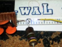
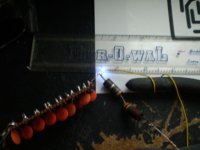
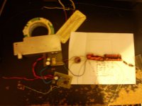
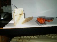
Here are the pictures of today's tests.
enjoy!
jer
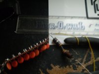
P.S. the scale on the ruler is in 1/10".
This test was done at this level.
However increasing the drive that much causes the Fet's to run rather warm.
I did not measure the current draw from the main supply and I am sure that it was quite high from the heat that the FET's produced.
Especially for not pulling any constant arcs, But, There were no failures.
These are IRF510's and using a FET with a lower Rds such as an IRFZ42 or similar this may not be an issue.
Using the lower drive voltage the IRF510's hardly get warm at all ,and ,will require a very minimal heatsink area.
Even though I was able to get close to an extra 1KV out of it doesn't justify the higher voltage drive as two more stages of the multiplier can do this without causing excessive current and heating of the FET's.
Due to the heating of the FET's it seemed to also cut down on the available current required to maintain a constant arc as well.
Even though maintaining a constant arc is not the goal it is a good test of performance and durability nevertheless.
I also made I slight change of the FET's bias configuration and I had a slight improvement with that and I will post a revised schematic when it is finished and off of the breadboard.
The one reading of 4.85v from the meter was thru a 1megohm resistor off of the divider and seemed to coincided with the reading of the scope waveform with the 10x setting on the probe and not going thru the 1megohm resistor.......hmmmm.
This is were I question the accuracy of the meter a little,But this discrepency is with the readings on a couple of ranges not being exactly the same with just the decimal point changing place.
But after a few more tests showed that my voltage divider is exactly 1000:1 and with in about .1% error if not better.
good enough for this application any how.
Here are the pictures of today's tests.
enjoy!
jer
P.S. the scale on the ruler is in 1/10".
Attachments
-
 BIAS SUPPLY SETUP.jpg125.8 KB · Views: 488
 -
 ARC.jpg78.5 KB · Views: 342
 -
 5Kv OUT CROSSHAIR IS 0V.jpg69.8 KB · Views: 332
 -
 OUTPUT WAVEFORM THRU 10X PROBE.jpg71.9 KB · Views: 60
 -
 OUTPUT OF DIVIDER THRU 1 MEGOHM RESISTOR.jpg59 KB · Views: 61
 -
 OUTPUT OF DIVIDER.jpg52.4 KB · Views: 70
 -
 GATE DRIVE THRU 10X PROBE.jpg459.6 KB · Views: 62
 -
 555 DRIVER OUT 1X PROBE.jpg64.8 KB · Views: 64
 -
 FET SOURCE OUTPUT 1X PROBE.jpg70.7 KB · Views: 65
Last edited:
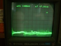
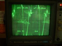
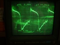
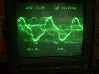
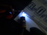
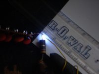
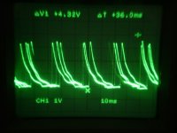
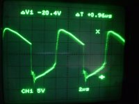
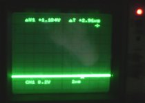
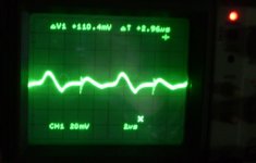
Here are some pictures of arcing in action and a shot of the output voltage waveform while it is arcing.
Sorry for them being a little blurry, If I do anymore I will take the time to make them as sharp as possible.
Again the scope setting is 1Kv per division and the cursors are crosshair 0v and the X is 4.32Kv
Enjoy !!!
jer
Sorry for them being a little blurry, If I do anymore I will take the time to make them as sharp as possible.
Again the scope setting is 1Kv per division and the cursors are crosshair 0v and the X is 4.32Kv
Enjoy !!!
jer
Attachments
I was able to clean up the gate drive signal today with a 100 ohm resistors in series with the gate lead today.
Doing this got rid of the ringing and cleaned it up a lot as well as allowing me to raise the gate drive supply to 15v.
I hardly get any interference lines at all on my TV now.
This is a very good thing and the FET's run much cooler than they did.
I had got a full 5kv out of it with 300v of ripple and it was running reliably and fairly cool at full tilt.
Until I got to poking around with a cap on one of the gates and popped an FET.
I ended going thru 3 or 4 Before I got it back running again.
If a gate becomes ungrounded from its pull down resistor this causes the FET to turn full on therefore blowing it, As there is only the resistance of two turns of wire as a load for each FET.
A short circuit at DC if you will.
This is probably because my solderless breadboard is old and worn out and this won't be an issue once everything is mounted and soldered together.
When I first designed this circuit I was using a single IRFZ42 and this happened all of the time only that they were so durable that all that would happen is the current would melt the solder connection to the FET and the supply wire would pop off saving the fet.
It eventualy wore out and it failed too due to heat, which is what forced me to use an IFR510 ,because I had lots.
The IRF510's work but good high current switching FET's are definitely better for this application.
Once I got back to square one every thing worked flawlessly and I ran it for several hours with a gate drive voltage of 15v and an output of 4.7KV.
Also I took the FETS of off my big heatsink and mounted them to a .080" X 24 square inch piece of aluminium plate and did some temp readings.
At full on it held at a cozy 85 degrees Celsius for 2 1/2 hours.
At 4kv about 65 to 70 degrees Celsius.
And below that 50 degrees Celsius and cooler as the FET's were just warm to the touch.
So with the second multiplier stage I will easily be able to get back to the 5kv to 7.5kv range to run my ESL without causing any extra stress or heat on the fets.
I will build another one to use for testing coatings with better and heavier duty parts.
Although this one will suffice for now.
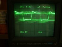
Here is a picture of the new Gate Drive Signal full on.
jer
Doing this got rid of the ringing and cleaned it up a lot as well as allowing me to raise the gate drive supply to 15v.
I hardly get any interference lines at all on my TV now.
This is a very good thing and the FET's run much cooler than they did.
I had got a full 5kv out of it with 300v of ripple and it was running reliably and fairly cool at full tilt.
Until I got to poking around with a cap on one of the gates and popped an FET.
I ended going thru 3 or 4 Before I got it back running again.
If a gate becomes ungrounded from its pull down resistor this causes the FET to turn full on therefore blowing it, As there is only the resistance of two turns of wire as a load for each FET.
A short circuit at DC if you will.
This is probably because my solderless breadboard is old and worn out and this won't be an issue once everything is mounted and soldered together.
When I first designed this circuit I was using a single IRFZ42 and this happened all of the time only that they were so durable that all that would happen is the current would melt the solder connection to the FET and the supply wire would pop off saving the fet.
It eventualy wore out and it failed too due to heat, which is what forced me to use an IFR510 ,because I had lots.
The IRF510's work but good high current switching FET's are definitely better for this application.
Once I got back to square one every thing worked flawlessly and I ran it for several hours with a gate drive voltage of 15v and an output of 4.7KV.
Also I took the FETS of off my big heatsink and mounted them to a .080" X 24 square inch piece of aluminium plate and did some temp readings.
At full on it held at a cozy 85 degrees Celsius for 2 1/2 hours.
At 4kv about 65 to 70 degrees Celsius.
And below that 50 degrees Celsius and cooler as the FET's were just warm to the touch.
So with the second multiplier stage I will easily be able to get back to the 5kv to 7.5kv range to run my ESL without causing any extra stress or heat on the fets.
I will build another one to use for testing coatings with better and heavier duty parts.
Although this one will suffice for now.
Here is a picture of the new Gate Drive Signal full on.
jer
Attachments
I am very happy with this configuration so far.
It only draws .45 amps when it is full on and no more than 1.8 to 2 amps drawing a small gaped continuous arc and around 1 amp for mild arcing.
It does draw 3.45 amps when the multiplier stage is shorted this is much better than the way it was when I first started.
I'm sure that it would do fine on a 10 to 20 watt wall transformer.
right now it is running on a 18v supply from a 25.2Vct 2amp transformer found at Radio Shack.
In fact all of the parts came from there except the switching transformers as they are just common line chokes torn out of some old PC supplies.
I don't have enough resistors at the moment to pull some power output tests.
But, I will do this on the next one as this is mainly to bias my ESL's.
Knowing me I like to push things beyond there limits and so far this is the maximum that I can get out this circuit and has proven to be very reliable so far the way it is.
Besides blowing a few FET's in the devolepment process this power supply is made compleatly of junk box parts and is quite versatile.
Being that it is variable from 0v to 4kv or more.
It has plenty of current to not drag down the output voltage if a breakdown and arc should occur.
It can also be seen on a scope exactly what the voltage is, when this breakdown happens.
This is perfect for testing high resistance coatings and such as it also has an output for direct reading of the output voltage with a common DMM at 1v per 1000v.
I will now get on with finishing the construction of this project so that I can start doing some real world tests.
jer
Last edited:
Just a few minutes ago I finished my power supply and it is ready for mounting in a box.
I had one problem to contend with and that was a parasitic niose and ringing problem that resulted in two more blown FET's trying to solve it even though it was working just fine.
Moving the output transformer off of the main board solved this as it was much to close to one of the FET's and input transformer.
Also I was able to lower the frequency from 160khz to 100khz with no major changes by just changing one capacitor on the 555 chip.
It actually Improved my output very slightly like 2 or 3 percent maybe.
It now outputs 10.32Kv with only 6% ripple at full on even with 7 of the dreaded 1N4007 diodes right in the middle of the 26 stage High Voltage multiplier.
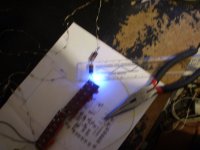
Here are some pictures of the thing in action as it is quite impressive pulling a continuous arc about a half of an inch long and better, and, one showing the corona discharge with the voltage cut back just enough to stop the continuous arcing.
Sorry,But I was too excited to note what the voltage was on the second shot and I am guessing around 8Kv to 9Kv.
Again I apologize for the blurry shots as the batteries in my camera were low and I couldn't hold it steady long enough for it to scan the shots. (He,he,he,sorry!)
jer
I had one problem to contend with and that was a parasitic niose and ringing problem that resulted in two more blown FET's trying to solve it even though it was working just fine.
Moving the output transformer off of the main board solved this as it was much to close to one of the FET's and input transformer.
Also I was able to lower the frequency from 160khz to 100khz with no major changes by just changing one capacitor on the 555 chip.
It actually Improved my output very slightly like 2 or 3 percent maybe.
It now outputs 10.32Kv with only 6% ripple at full on even with 7 of the dreaded 1N4007 diodes right in the middle of the 26 stage High Voltage multiplier.
Here are some pictures of the thing in action as it is quite impressive pulling a continuous arc about a half of an inch long and better, and, one showing the corona discharge with the voltage cut back just enough to stop the continuous arcing.
Sorry,But I was too excited to note what the voltage was on the second shot and I am guessing around 8Kv to 9Kv.
Again I apologize for the blurry shots as the batteries in my camera were low and I couldn't hold it steady long enough for it to scan the shots. (He,he,he,sorry!)
jer
Attachments
Last edited:
I have never used a Megger,But basically this is what I am trying to accomplish only on a bit larger scale.
A megger generally has a 1000v limit and measures up to 400megohms,this equates to 25ua (.000025 amps).
With 10Kv, this will allow me to measure up to 4gigohms for the same 25ua of current and up to 100gigohms for 1ua of current.
Measuring current levels that low can be very difficult so raising the supply voltage decreases this margin of error.
10Kv is a lot of voltage and is more than enough for what I want to do.
But, I did need a power supply that could supply enough current so that the voltage does not droop when any loads are connected to it.
Such as the resistor divider string for measuring the voltages, as well as any load connected to it.
My last version had issues about this.
Even though I was able to get a measurable 7.5Kv it seemed that the voltage was much higher when I disconnected the resistor divider string due to the arc length.
Also I figured out that my original divider string was pulling as much as 3.5 watts off of the supply as well at 7.5kv.
This one pulls about .75watts (max at 138.65 megohm) at 10kv a factor of 1/5 the power drawn for measuring the output voltage.
The other cool thing is that by using my scope to monitor the output voltage I can see exactly what the voltage is when a breakdown occurs and what the voltage is when the arc stops conducting as well as the time it takes for the power supply to charge back up starting the whole cycle all over again.
As shown in post #28.
jer
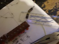
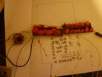
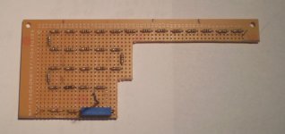
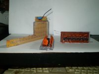
Today I got the high voltage resistor divider made.
It has twice the value of my original one.
It consists of 30 x 10 megohm resistors in series and individualy measured with a total resistance of 298.44 megohms with a 270k ,27k and multiturn 20k trimmer in series on the tail for calibration of the final divisor.
My last divider had as much as 600v across the 10megohm resistors this was a bit too high(for my liking) although they worked just fine.
In this new configuration there will be less than 350v across each one when it is full on.
In normal operation (250v at 7.5kv) it will be much less and will help to maintain the accuracy throughout its operating range.
I had to grind off all of the extra pads from the bread board material so that no flash over can occur between them as 10Kv will jump a 1/2" gap with no problems.
I will also run a bead of clear silicone sealant down the resistors and sandwich them in between acrylic sheet on the top and bottom as well.
This should be enough to keep any of the corona from leaking out.
I had found some more capacitors so I will added two more stages to one of the multiplier boards to fill it up and this will make a full 28 stages.
Here are some pics of what I have done so far.
jer
Attachments
Last edited:
I have the supply pretty much done today except for the buffered output for the meter and scope.
During testing it was drifting lower due to the FETs heating up a little fan solved this issue and is now rock solid stable.
Much more accuracy of control will be had when I finish the buffered output and regulation feedback.
I am able to adjust to a 10v accuracy per 1000v according to my meter as it sits.
So, I am expecting a 1v resolution if not better with the feedback circuit.
Loading resistance of the meter and scope play a big part in this so it is definitely needed to be real precision.
I changed my output transformers primary from 2 turns to 1 turn per winding as I had it originaly as well as adding 2 more stages on the voltage multiplier.
It now puts out about 12.5kv at least for a peak.
This is an impressive voltage when drawing some arcs and the thing will do so continuously.
When you watch the thing in the dark you can see the little corona fingers reach out across the gap of about slightly more than 1/2" in length until you get close enough for it to jump the gap,SNAAPPPP!!! AHH,HA,HA,HA !!
This is about the voltage I had when I first started messing with ESL's and started testing coatings and such with my very first supply.
It was made from the power transformer of a Fender Vibro Champ amp (337v).
Here are some pictures of it sitting quietly idling at 11Kv and a shot of the ripple voltage at 200V per division.
Next I am going to work on mounting it in a chassis so that I can use it and as well as finish the output buffer for the meter and regulation feedback circuit.
When it is up into 8Kv or more HV is every where and I get a little tingle even off of the ground side when I first touch it in order to adjust the voltage. He,he,he
enjoy!
jer
Attachments
Last edited:
Yesterday I got the HV components coated with very generous coats of 2X clear acrylic spray and encapsulated in clear silicone using some old broken CD cases.
This will greatly help contain the high tension and keep it from getting in to things (I hope) as it produces a peak voltage of 13.25kv!
I just found some IRFZ42's and I will try them when I get everything mounted as the 13.25Kv quickly reduces to 12.5Kv after it gets turned on even with a fan.
I believe this issue will go away with the IRFZ42's or I may just leave them and use them in the next project.Hmmm.........
The fact that it is stable at 11Kv is good enough for me.
jer
Attachments
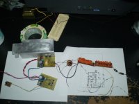
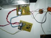
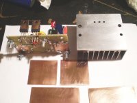
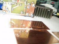
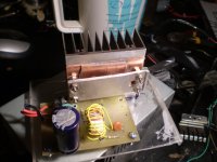
Today I have the heatsink assembly finished and it should take care of any instantaneous spikes of heat when they occur with copper spreaders and a fan as well, as the FET's and all of the pieces were lapped with some 600 grit wet sandpaper.
All of the boards are now mounted and ready to be rewired.
As well as the High voltage units are cased in their own little plastic boxes and sealed in some clear silicone sealant to insure that the high voltage is self contained so that no arcing to the metal box or any other parts can occur.
jer
All of the boards are now mounted and ready to be rewired.
As well as the High voltage units are cased in their own little plastic boxes and sealed in some clear silicone sealant to insure that the high voltage is self contained so that no arcing to the metal box or any other parts can occur.
jer
Attachments
I like your High V set up.......an i well take a shot that you are doing this for esl BIAS.
i HAVE found that the Acoustat type set works vary good..All but the 50mohm at the end bfore the panel....i have dropet it to 6mohm an the sounds faster.... like with the 50m it run out of v, an you can here the sage....now this is not a bad thing...is the bias your are woring on to be stiffer.... an not sage...an let you set any v...i use a varack ..
thanks
I have been working on the bias setup in the ML panles an well say the the 6 mohm befor the panel...Has a BIG affect on the Sound!..... i like a 1/2-1watt....the logan thay have 1/8 ohm frist then 1/4 an two miney....for me...if you panes sound roll off...or To brite this re.can chang it...lot of work on the Bias/panels sound...still to do...for all.
- Status
- This old topic is closed. If you want to reopen this topic, contact a moderator using the "Report Post" button.
- Home
- Loudspeakers
- Planars & Exotics
- how can test the stator insulation and mylar coating?