first to build a complete esl i would test if the mylar coating and stator insulation are good. For the mylar i diluited 8gr elvamide in 100cc ethanol but the document on audiocircuit say it have to be further diluited with equal volume of "anhydrous A.R. or L.R. grade methanol",
that i haven't, can i use ethanol again?. About the stators i would use a perforated metal sheet but im not sure of the perfect insulation. It's possible to make some electric test with a little piece of it and a little sheet of coated mylar to see if the sistem work good?
that i haven't, can i use ethanol again?. About the stators i would use a perforated metal sheet but im not sure of the perfect insulation. It's possible to make some electric test with a little piece of it and a little sheet of coated mylar to see if the sistem work good?
I use my bais supply connect between a screw driver and the stator.
Scanning the the surface area of the stator with the screwdriver will show any leaks evident in the stator coating.
Make sure that you use at least a 1 megohm resistor in series with the bais supply and the screwdriver.
The resistor will limit the curent draw and save the diodes in the bias supply from shorting due to excess current draw from an arc when a leak is discovered. jer
Making your own coating material isn't easy. A lot of times you'll end up with unsatisfactory results. I would suggest you look into purchasing the right stuffs. I have been using a permanent antistatic solution with great successes.
Wachara C.
hi wachara, i'm interested. This will not add mass to the diagphram?
Hi,
You could use a piece of household Aluminum-foil. Connect the HV-supply to the stator at one end and the foil to the other end. The foilswill be sucked towards the stator. Raise voltage of the HV-Supply and listen and look where flashovers occur. It´ll start with tickling noise all over and eventually single clean flashovers pop up. If the flashover is strong enough it pounds small pickles into the foil surface. So You can easily detect where a spark flew and the insulation fails.
jauu
Calvin
hi wachara, i'm interested. This will not add mass to the diagphram?
Any coating adds mass, most of the time you don't know how much because this information is not provided I(while it should). Check out the previous discussions about coatings on this forum, you will also see there is much better to get than elvamide.
Using a wire stator instead of perforated sheet seems to be the best way to make a reliable esl.
Also look for a neonoscillator at the output stage of the HV-supply as it indicates the amount of charge supplied to the membrane
Over here in the states some of us have have been using a product called licron and licron crystal.
I first discovered "LICRON" in 2003 and "LICRON CRYSTAL" hit the market in about March of last year.
I don't know if it is avaiable in your area but I'm sure that a suitable equivalent can be found.
On my original diagphrams I had used licron.
Its thickness was about .1mil to .3mil depending on how many coats were applied to my .25 mil mylar.
It worked great and still worked after 7 years of deliberate extreme environmental torture.
Upon disassembley of the panel there was no evidence peeling of the coating just a bunch of dirt, sand and salt stuck to the diagphram.
So, I then cleaned the diagphram with denatured alcohol and reassembled the panel and it worked with out any problems at all.
Due to the cleaning, The detail of the high end was restored that was lost becuase of the added mass of the dirt and sand.
Then I replaced one of the diagphrams and tried the licron crystal formula to do a comparison against the old formula.
The coating dried absolutely clear and the thickness was unmeasurable with my micrometer.
In the comparison test I did notice a slight increase in high end detail aswell.
This was only barley noticeable in an a/b comparison with the other panel of exact size made of the same material and construction only using the old formula as a coating that was 7 years old.
That had no degradation of performance since the day it was built after the cleaning.
I will find and post the links where I showed this procsess with lots of pictures and closeups of the surface of the diagphram as well.
Also the one ones where Charlie had redone his panels with the new formula too.
My little panels turned out to be pretty efficient and get exteremly loud usiing a 1:200 to 1:400 stepup ratio and diagphram size of 3.25" X 9.75" and a d/s around .075" (75mil).
I am able to get down to around 100hz or lower without excursion clipping with this setting while not sacrificing efficiency.
This type of clipping was only witnessed using a microphone and an o-scope when the panel was driven very hard and the clipping was very slight at that.
The stator coating I used was a double layer of powder coating.
This process has some bugs that need to be worked out and were the last panels that I made and the only ones that used powder coating.
Later on I had discover that had some leaks but nothing major, but, they wouldn't hold the 7.5kv bias that I was applying.
A few coats (6) of clear acrylic took care of that.
On my last test I used my Crown dc300a to power them at full power and a full 5kv to 7kv bias with an estimated 27kv p-p across the the stators.
This was a very extreme condition and was so loud the average joe would have vacated the room instantly.
They survived this condtion thru many cyclings of amplifier shutdown due to overheating.
In other words they brought that Crown to its knees.
But, It kept on going and still works perfectly to this day.
It is one heavy duty amplifier with unadequate heatsinks, IMO.
This went on for a good 1 1/2 hours until a leak devoloped along the edge of the screen and arced over to a sandwhiching bolt to the other side or to/or near the charge ring.
So, I then ran them in this condition for a while to see if any thing else would develop while I blew out the flames of the burning acrylic spacer material.
No other problems occured.
Upon disassemebly of the panel had found no damage to the diagphram, aswell as, no pinholes burned in the diagphram.
The leak was caused from a sharp end of the stator wire not buried deep enough in the insulating material used to seal the cut edges of the screen stator and it just happend to be near a bolt.
Originaly I used clear silcone as an insulating seal but during the refurbishment process I discovered that the clear acrylic spray did not bond the the silicone.
So questioning this as being unadequate in this area, I spent endless hours taking off the silicone and resealing the preimeter with clear nail polish.
I did have A hard time sealing that exact spot from leakage and I wasn't going to put that bolt back in, but I did, and figured that a problem would eventualy arise and it did.
This was the only flaw in the design I have found so far and is an easy fix for the next build.
I had also delibreately built the diagphram frame with an inside deminision of an 1/8" smaller than that of the stator to protect against such an occurence.
It worked, As the flashover went the other way to the bolt which is much farther away instead of going through the diagphram.
So, I merely cleaned off the burnt material and carbon residue resealed the bad spot and retested it for leakage and arc through and it is now ready to be reassembled for another go around.
That is were I had left off last summer as I had to rearange my equipment to solve some noise and ground loop issues and I still have to build two more variable bias supply prototypes that I had designed and put them in a proper enclosure.
As not to cause any risk of HV getting back into my equipment like last year.
I was lucky that nothing happend to any of it.
If you do a search on licron in the forum you will find two pages of threads on various ESL builds many of which I have never seen or read before.
So I guess I have some catching up to do aswell from 2006 when I was MIA due to my stupid mistakes in life (ha,ha,ha, live and learn the hard way). jer
Last edited:
Here those links.
This is an excelent thread and should be read from beginning to end.
Opps there was one diagphram where that coating came off I suspect it was due to improper cleaning and handling during the coating process and had occured when I cleaned the diagphram after 7 years of abuse. jer
http://www.diyaudio.com/forums/planars-exotics/109789-esl-diaphragm-coating-7.html#post2142822
http://www.diyaudio.com/forums/planars-exotics/109789-esl-diaphragm-coating-8.html#post2144443
http://www.diyaudio.com/forums/planars-exotics/109789-esl-diaphragm-coating-8.html#post2160477
Here are the ones when Charlie redid his panels with the new formual.
http://www.diyaudio.com/forums/planars-exotics/166280-jazzmans-new-stat-panels.html#post2174937
http://www.diyaudio.com/forums/planars-exotics/178623-diaphram-coating.html#post2401985
Cheers. jer
http://www.diyaudio.com/forums/planars-exotics/166280-jazzmans-new-stat-panels.html#post2174937
http://www.diyaudio.com/forums/planars-exotics/178623-diaphram-coating.html#post2401985
Cheers. jer
Over here in the states some of us have have been using a product called licron and licron crystal.
I first discovered "LICRON" in 2003 and "LICRON CRYSTAL" hit the market in about March of last year.
I don't know if it is avaiable in your area but I'm sure that a suitable equivalent can be found.
i'm trying to find this licron in my area but nothing for now (even on ebay and local web sites) maybe it's in some antistatic spray under different name...i'll ask to somebody who know this products
I am a bit scared of very high tensions and except some tube amplifier i never worked with them. For the safety its better to built a high frequency bias supply like this:
http://sound.westhost.com/p105-f5.gif
or a tipical cockcroft-walton schematic? Anyway which are the things to avoid while running the tests?
http://sound.westhost.com/p105-f5.gif
or a tipical cockcroft-walton schematic? Anyway which are the things to avoid while running the tests?
I haven't tried that circuit yet but I have been wanting to.
Most are using a 2kv to 3kv supply.
I used such a high voltage because I was maxing everything out to find the absolute maximum limits of the materials.
On an average 3kv to 4kv is very sufficient.
The D/S spacing is the final determining factor here.
Charlie's "The Jazzmans blog" describes a very good simple bias supply.
Yes ,you can get a zapp from them but on the norm the actual currents are too low to be lethal.
Although as with all high voltage circuits "proper care and precautions and rules must be practiced and hendered too".
The voltages and current comming out of the stepup transformers are much more dangerous than the bias supply when driven to a high level.
If you are familar with tube circuits then you should already know the rules and I won't ponder on them.
I will dig up the schematic of my circuit and post it as the topology is no special secret.
It is a very simple switching type supply starting with 555 timer as well.
The only reason I haven't posted it yet was because I wanted to be sure that anyone could build it and have it work the first time one fired it up.
The only problem I have with it is that the resonate frequency of the transformer is right at the edge of the maximum frequency that the 555 can oscillate.
The transformers are just some little toriod cores that I salvaged out of some dead computer power supply's and are nothing special.
I have popped a couple of chips in the design process and found some that would not oscillate at those frequency's at all( >150khz).
But once tuned it proved very relieable and is variable from 0v to 7.5kv with a load.
It will build up a charge high enough to jump a 1cm gap and hold a continous D.C. arc at around 3mm to 4mm.
I have pictures of this in another thread.
I was also thinking about adding a feedback circuit aswell to help with constant regulation although it really isn't much of an issue but the circuit would allow a point for a safe voltage measurement using a DMM or a digital panel meter module.
Regards. jer
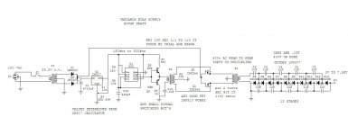
Ups, lets do it hard way when the easy one is on avail?!Here is the basic schematic of my bias supply.
Most values where found thru trial and error.
But most of them are as it sits now.
And this is for any one who wishes to use it. jer
I would not recommend using such design.
To be totally honest with you it's an example how not to do it.
Implementation kills the idea
Why don't you use two 230/12 trafos back to back? Medical grade.
Guaranteed isolation!
If one needs regulation, just put wirewound trimpot of 5-15 W as voltage divider in between(@12V). There is no power cosumption anyway...
If you insist upon superior qualities, then I would replace 555 and accociated "driver" of yours with IR2153, half bridge power topology would be reasonable as well.
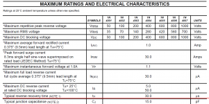
What is the recovery time of the 1N4007? Go check for your own amusement.
Changing gate voltage for regulation is plain wrong, unless it's HF amplifier stage. May that's what you've discovered.
Last edited:
Alex,the circuit works fine as is.
I will be changing the 555 to some other type of variable oscillator that has a wider and higher range for versatility.
I would have loved to use an IR2XXX mosfet driver but that would cost money and I don't have any.
But it sure would have made the design a whole lot easier as my intention was to use PWM for regulation.
A 15 watt wire wound pot would cost more than the all of the solid state devices in the circuit.
I do have a 50 watt 100 ohm wire wound pot that I was going to use but the element is open so I couldn't use it.
The typical recovery time of a 1N4007 is 2us and my very worst case (although marginal) requirement it is 5us.
I had questioned this myself but when I tested the output with a single diode I found that it was switched just fine so then I tested them with a full wave bridge and got I perfectly uniform fullwave rectified waveform across a resistance load.
My intent was not to have such a high switching frequency but thats the way it turned out because the cores I used were pulled and used as is and unmodified from dead computer switching supply's.
This version is a far cry from my original single mosfet design which grossely over heated and was extremely inefficient.
It took every bit of the 50 watts that supply transformer could muster up and ran quite hot because of it.
This version runs relieabily and the mofets are cool to the touch, Including the power transformer.
It is made of junk box parts and cost me next to nothing to build and I have enough parts to build six more but I only need two.
Yes there are alot of improvements that can be done and what is exactly wrong with the variable gate drive class b stage anyhow it works, it serves its purpose and serves it well.
Originaly I was going to vary the voltage supplying the mosfets but when I stumbled upon the output voltage of the 555 varying with the supply feeding it while maintianing its frequency, it just made things a whole lot easier.
It runs with about 300v of ripple at 7.5kv with a load thats 4% ripple.
That can be improved with a simple filter stage.
Much simpler than if it were running at 60hz and at >100khz you can't hear it anyway.
I have built many 60hz bias supply's and is why I had suggested that one should take a look at Charlie's web site " The Jazzmans blog " which describes a simple 60hz bias supply that works and works well.
I knew that I should not have posted my design as I had already stated that it was unfinished and needed to be improved so that if one did try to build it that it would work without a hitch.
As it took some tinkering to get it right, not knowing the parameters of the cores that I used.
My design was not intended to just only power ESL's with.
It was a great learning experience of the topology and I have plenty other uses planned with the design aswell.
Trust me I didn't just pop a few 555 chips, I took out a few mosfet along the way aswell.
Luckily they were dirt cheap and readily available at the local Radio shack or electronic parts store.
You can say that about the IRxxxx stuff.
Unforunately Radioshack is the only thing In my area and shipping for mail order would cost twice as much (if not more) as the cost of the parts I need at the moment.
After all, isn't it why they call it DIY?
Best regards. jer
I did not say it does not work. Neither trying to step on your throat, so to speak. I've said it's improper way of doing things.
Eastern Germany's made Trabant falls into definition of a CAR. One guy travelled across the states on lawn mower
Is it a way to go?... For for other inexperienced guys to replicate?...
For instance 150kHz period is 6.7uS, half of that is 3.3 uS.
Use of diodes with 30uS recovery time which is 10 times longer than conduction time is plain wrong.
Attachments
Last edited:
Hi,
I use Staticide 6300 for coating, and it works very well.
Wachara C.
Have not you said it does not dry out?
- Status
- This old topic is closed. If you want to reopen this topic, contact a moderator using the "Report Post" button.
- Home
- Loudspeakers
- Planars & Exotics
- how can test the stator insulation and mylar coating?