I've had several requests recently for information on upgrading Spectra's Ultrasonic bias power supply. Therefore, for the benefit of all, I am posting the related documents here.
Attachments
Andy, you're a star. Many thanks! MikeTherefore, for the benefit of all, I am posting the related documents here.
It does seem there is some confusion on whether the speaker wants an AC or DC input. One might assume that label on the speaker is correct, but who knows. The good news is that applying a DC voltage to an input intended for an AC input will do no harm. This is not true the other way around. If you can examine the circuitry and you see diodes or a bridge rectifier close to the input jack, you can safely assume its intended for an AC input.
I've only seen photos of the Chinese panels. They do appear to be based on Acoustat's sheathed-wire design, and I'm assuming they continued with Spectra's segmented stators. They look to be solidly and neatly constructed. I have no idea what they used for a conductive coating.
Hi.
I looked into the woofer's box, and saw diodes and the bridge rectifier so I guess AC input is correct. I must either find a good 9V AC transformer or a DC transformer with a suitable voltage.
Thank you a lot!
-Morten.
Hi.
I looked into the woofer's box, and saw diodes and the bridge rectifier so I guess AC input is correct. I must either find a good 9V AC transformer or a DC transformer with a suitable voltage.
Thank you a lot!
-Morten.
No need to go too nuts finding a "good" 9 VAC transformer. The current requirements are very low, and the transformer is far removed from any portion of the audio circuitry. Which is to say I doubt very much you could hear a difference between a cheap-o wall transformer and something more substantial.
Granted, I replaced my Spectra 4400's wall transformers with small toroidal transformers, but only because someone gave them to me and they were already nicely mounted in boxes, ready to plug-n-go. So why not?
Lack of LF response over time?
Hi Andy,
I thought you might be interested in knowing that my friend came to stay for a couple of days and we dismantled the 6600s in turn and I replaced the LEDs in each of the small bias supply boards. I wasn't able to buy replacement LEDs with those little housings attached so the ones I bought had to be fashioned in such a way that they ended up being in the same position as thr originals. Nevertheless, that worked out well and they poke through the holes in the chasses.
We were careful when moving the panels over the baseboards (using a vinyl covering material for protection that my friend brought along) and I'm pleased to be able to report that the boards were left totally unmarked. We also took the opportunity to spruce them up a little with some furniture polish.
While everything appears to have gone well, I do have one concern that was completely the result of stupidity on my part - and I'm not ashamed to admit it.
After replacing the first LED (in the right channel unit), I wanted to be absolutely certain that it would light up (i.e. that I had polarised it correctly) before screwing the little board back into the so-called interface chassis. With each original LED partly hidden in its housing, I wasn't able to tell which lead was the anode and which the cathode. (Screwing the board back into the chassis was quite a feat in itself, definitely requiring two people and what I call a 'magnet stick' so that the nut/lock washer could be positioned and retained onto the end of the fastening screw each time before catching the thread). I also wanted to be certain that, in testing the LED, I wouldn't be powering up the 5KV bias voltage so I unsoldered the white wire from the corner of the board that appeared to feed the Cockcroft-Walton voltage multiplier. I should have realised that that was all I needed to unsolder. However, for some inexplicable reason, I decided to also unsolder a yellow wire situated between two 15K ohm resistors on the board, which seemed to be connected in some way to a two coil arrangement on the board as well as being one of the inputs (pin 3) of an LM13080 amplifier. Unfortunately, after clearing the solder around the wire in preparation for removing it, the wire would not come out through the hole in the board - I have a recent model Pace de-soldering tool and was using that for all wire and LED removals - because the wire had a little kink in the end of it. I ended up cutting off that very end of the wire. It was only when I went to resolder it back into the board later that I had a nasty feeling. That was when I noticed that it was a quite solid multi-stranded wire dark in colour, and I wondered if the strands might have been welded together at the very end before feeding through the board and soldering and that I had removed the weld. Perhaps it's of no importance but I'd like your comments. I also wondered if the wire might have been composed of a material other than copper due to its appearance. It certainly soldered back onto the board track well enough but I am concerned that, long term, I could end up with a problem, maybe resulting in either no, or reduced, bias voltage.
Do I have a right to be concerned, or am I worrying for nothing?
I had actually downloaded a schematic for the bias and signal feed before remembering that there is also one in the back of the 6600's Owner's Manual. In comparing the two drawings, I noticed a difference: In the one in my Owner's Manual, the wire I'm concerned about is apparently connected to the bottom of what I will tern the primary coil (the left hand of the two in the schematic), while In the modified diagram, that wire looks like being conncted to another very small coil that is (inductively?) coupled to the top of the secondary (right-hand) coil. Is that some sort of feedback to regulate the output? Actually, I've tried to figure out what's actually going on there but I'm lost I'm afraid. That yellow wire ends up being in close proximity to a red wire (which sits inside some clear tubing) and both wires are covered by black sleeving so I am unable to see what is actually happening there. I decided I had possibly done enough damage by this time so I certainly didn't investigate further! However I did a resistance check and, from memory, the two wires were not physically connected.
Needless to say, when I replaced the LED in the left-hand unit, I left that yellow wire attached to the board and only disconnected the white wire to the voltage multiplier when testing the LED.
While I had each chassis out, I checked the 5 watt 75K ohm, 680K ohm amd the huge 50 watt 100K ohm resistors and all were in the vicinity of their specified values. (My elderly Fluke meter was unable to check the 500M ohm resistors feeding the diaphragms). Everything looked fine too - no unexpected discolouration anywhere and all the electrolytic caps looked to be in good condition too. I had also forgotten just how heavy the pairs of signal transformers are.
After restoration, we spent some time repositioning both speakers for optimum toe-in and relation to the walls of my listening room. They appear to be performing extremely well and there is definitely no lack of deep bass so I'm not sure why I was concerned about that before. The channel balance seems excellent too so, hopefully, all will be fine from now on.
Any comments always welcome and thanks again for your earlier advice.
Sorry for the delayed response…somehow I missed your post earlier.
I do not have a ready explanation your change of bass performance. I’ve never heard of the diaphragm increasing in tension. However, a decrease in tension has been reported occasionally, but I don’tthink that’s the issue in your case, as the symptom of insufficient tension is usuallya rattling or slapping noise on large bass notes.
I also do not suspect a decrease in bias voltage, whichcan happen. However, that typically results in a loss of efficiency across the entire audio range, not just in the bass region.
You may want to check the pin-plug connections betweenthe interface and panels. If one or moreof connections are faulty, this could result in a loss of bass performance if one or more panel segments is not producing at full volume.
If the connections seem okay, you might want to check the values of the six resistors mounted on the printed circuit board. If one or more of them has gone open-circuit, or significantly increased in value, this could also result in decreased bass output.
I’m really just shooting in the dark here, so if you can investigate my suggestions above, we might gain information that could help todiagnose your problem. Of course, this is all assuming the problem exists in the speaker. Do you have the ability to try a different amplifier?
Hi Andy,
I thought you might be interested in knowing that my friend came to stay for a couple of days and we dismantled the 6600s in turn and I replaced the LEDs in each of the small bias supply boards. I wasn't able to buy replacement LEDs with those little housings attached so the ones I bought had to be fashioned in such a way that they ended up being in the same position as thr originals. Nevertheless, that worked out well and they poke through the holes in the chasses.
We were careful when moving the panels over the baseboards (using a vinyl covering material for protection that my friend brought along) and I'm pleased to be able to report that the boards were left totally unmarked. We also took the opportunity to spruce them up a little with some furniture polish.
While everything appears to have gone well, I do have one concern that was completely the result of stupidity on my part - and I'm not ashamed to admit it.
After replacing the first LED (in the right channel unit), I wanted to be absolutely certain that it would light up (i.e. that I had polarised it correctly) before screwing the little board back into the so-called interface chassis. With each original LED partly hidden in its housing, I wasn't able to tell which lead was the anode and which the cathode. (Screwing the board back into the chassis was quite a feat in itself, definitely requiring two people and what I call a 'magnet stick' so that the nut/lock washer could be positioned and retained onto the end of the fastening screw each time before catching the thread). I also wanted to be certain that, in testing the LED, I wouldn't be powering up the 5KV bias voltage so I unsoldered the white wire from the corner of the board that appeared to feed the Cockcroft-Walton voltage multiplier. I should have realised that that was all I needed to unsolder. However, for some inexplicable reason, I decided to also unsolder a yellow wire situated between two 15K ohm resistors on the board, which seemed to be connected in some way to a two coil arrangement on the board as well as being one of the inputs (pin 3) of an LM13080 amplifier. Unfortunately, after clearing the solder around the wire in preparation for removing it, the wire would not come out through the hole in the board - I have a recent model Pace de-soldering tool and was using that for all wire and LED removals - because the wire had a little kink in the end of it. I ended up cutting off that very end of the wire. It was only when I went to resolder it back into the board later that I had a nasty feeling. That was when I noticed that it was a quite solid multi-stranded wire dark in colour, and I wondered if the strands might have been welded together at the very end before feeding through the board and soldering and that I had removed the weld. Perhaps it's of no importance but I'd like your comments. I also wondered if the wire might have been composed of a material other than copper due to its appearance. It certainly soldered back onto the board track well enough but I am concerned that, long term, I could end up with a problem, maybe resulting in either no, or reduced, bias voltage.
Do I have a right to be concerned, or am I worrying for nothing?
I had actually downloaded a schematic for the bias and signal feed before remembering that there is also one in the back of the 6600's Owner's Manual. In comparing the two drawings, I noticed a difference: In the one in my Owner's Manual, the wire I'm concerned about is apparently connected to the bottom of what I will tern the primary coil (the left hand of the two in the schematic), while In the modified diagram, that wire looks like being conncted to another very small coil that is (inductively?) coupled to the top of the secondary (right-hand) coil. Is that some sort of feedback to regulate the output? Actually, I've tried to figure out what's actually going on there but I'm lost I'm afraid. That yellow wire ends up being in close proximity to a red wire (which sits inside some clear tubing) and both wires are covered by black sleeving so I am unable to see what is actually happening there. I decided I had possibly done enough damage by this time so I certainly didn't investigate further! However I did a resistance check and, from memory, the two wires were not physically connected.
Needless to say, when I replaced the LED in the left-hand unit, I left that yellow wire attached to the board and only disconnected the white wire to the voltage multiplier when testing the LED.
While I had each chassis out, I checked the 5 watt 75K ohm, 680K ohm amd the huge 50 watt 100K ohm resistors and all were in the vicinity of their specified values. (My elderly Fluke meter was unable to check the 500M ohm resistors feeding the diaphragms). Everything looked fine too - no unexpected discolouration anywhere and all the electrolytic caps looked to be in good condition too. I had also forgotten just how heavy the pairs of signal transformers are.
After restoration, we spent some time repositioning both speakers for optimum toe-in and relation to the walls of my listening room. They appear to be performing extremely well and there is definitely no lack of deep bass so I'm not sure why I was concerned about that before. The channel balance seems excellent too so, hopefully, all will be fine from now on.
Any comments always welcome and thanks again for your earlier advice.
I well be the first to say........... I would gess most here have never seen..or even new of a pr of Acoustat 6600......But....
"A picture is worth a thousand words"
In 2017-18 most have cell phone ...that can take a good pic.....gezz just saying.....
Have fun ...good luck...."Happy holidays" too Andy an all...
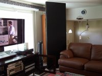
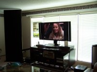
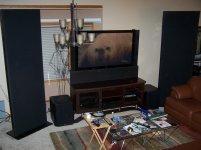
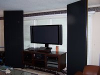
I have been very fortunate having owned 2 pairs of spectra 6600's and a pair of spectra 66's. I have since sold one of the pr of 6600's and the pair of 66' s to person near Edmonton Alberta Canada.
The pair I have left have moved several times across Canada that will be my last speaker ...jokingly I have said to my wife bury me between them..and I will be in heaven
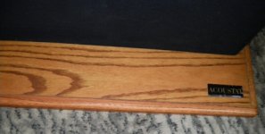
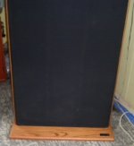
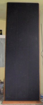
I have attached some photos of them

The pair I have left have moved several times across Canada that will be my last speaker ...jokingly I have said to my wife bury me between them..and I will be in heaven
I have attached some photos of them
Attachments

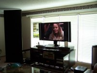
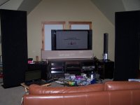

The Spectra 6600's that I enjoy in some of my listening areas. The rooms may not be ideal but the music is always pure enjoyment
Attachments

I have been very fortunate having owned 2 pairs of spectra 6600's and a pair of spectra 66's. I have since sold one of the pr of 6600's and the pair of 66' s to person near Edmonton Alberta Canada.
The pair I have left have moved several times across Canada that will be my last speaker ...jokingly I have said to my wife bury me between them..and I will be in heaven
I have attached some photos of them
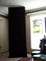
You were obviously lucky in your choice of wives. For most anyone else, bringing a pair of speakers into HER living room that look like the obelisks from 2001 would get HIM buried then and there.

An externally hosted image should be here but it was not working when we last tested it.
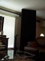
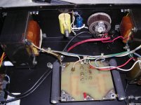
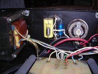
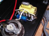
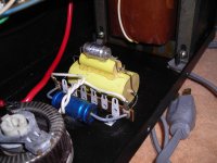
Here - hopefully - are three images of sections of my right-hand channel Spectra 6600. If they don't appear, I might have to ask for assistance on how to upload images. These ones are on my Google Drive.
An externally hosted image should be here but it was not working when we last tested it.
I've reduced the size of each of the files to 12 percent of that I uploaded earlier and I've uploaded these new images in a new folder to my Google Drive. The original resolution was such that they still look good.
Hopefully, this will produce a more satisfactory result here.
This may help...
How to attach images to your posts.
Many thanks, Bolserst. I previously clicked on the FAQ option and carried out a search for 'Uploading images' but it returned nothing so I didn't look any further. I don't think I would ever have found the answer without your assistance so thanks again. I've printed out the relevant article and will try it out shortly.
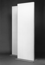
Spectra 6600 Factory Photo
I finally had a chance to rummage through my Acoustat files, and found this black-n-white factory photo of a pair of Spectra 6600's. Unfortunately there's nothing in the photo to lend a sense of scale - it would have been better if these had been "lifestyle" shots instead of "glam" shots.
I have some similar photos of other Spectra models if anyone is interested.
Attachments
Help needed for Acoustat 2+2 (MK121-2B)
Hey guys! Need your help. I am trying to replace the old capacitors in my MK121-2A interfaces.
I have (3) total stacked together (see pics). The values I can read are 250V 10uf, 200V .47uf and 27 000 160v that's the little electrolytic cap on the end of the (2) yellow caps.
The schematic I have doesn't show the electrolytic and the .47uf is listed as a .01uf.
What should these values be? And should the electrolytic cap be left off or what should replace it.
I've already changed out the binding posts and old Monster wire and put on longer, bigger gauge AC Power cable.
Thanks for your help!
Attachments
Last edited:
- Home
- Loudspeakers
- Planars & Exotics
- Acoustat Answer Man is here